
Wind energy system and method for using same

a technology of wind energy and wind energy, applied in the direction of machines/engines, liquid fuel engines, electric generator control, etc., can solve the problems of increasing driveline maintenance, increasing the cost and complexity of maintenance actions, and inability to sustain energy supply

Active Publication Date: 2013-10-31
HFI IP HLDG LTD
View PDF9 Cites 30 Cited by
  • Summary
  • Abstract
  • Description
  • Claims
  • Application Information

AI Technical Summary

Benefits of technology

The present invention solves many of the problems with conventional wind energy systems. It is smaller, less expensive, and easier to install. It also has the following advantages: (i) the turbines can face the wind from multiple directions; (ii) they have a mechanism to reduce mechanical drag; (iii) they can absorb fluctuations in wind power to provide a constant level of power output; (iv) they are less prone to vibration and damage from wind power; (v) they have an integrated energy storage system, which enables controlled energy output without energy loss; (vi) they have a combined driveline and generator system, which allows for independent control of the generators and rotor system; (vii) they have a hybrid power option for constant energy supply; (viii) they incorporate load sensors to automatically adjust the tower height based on load stress or wind speed, thereby avoiding the need to turn the rotors off and cease energy production; and (ix) they can be lowered for maintenance. Additionally, the present invention incorporates a bat deterrent system that is not found in any existing wind energy systems.

Problems solved by technology

In addition, the cost and complexity of a maintenance action are significant due to the fact that the gearbox and generator are on the top of a fixed tower that cannot be lowered.
Because this availability of energy is fluctuating, it cannot be relied upon for sustained energy supply.
Structural disadvantages of conventional wind energy systems include, but are not limited to, the following: (i) the turbines only turn to face the prevailing wind on a horizontal axis; (ii) they do not include a mechanism for reducing driveline mechanical drag relating to available wind speed; (iii) they do not provide a system for absorbing fluctuations in wind power so as to provide a constant level electrical power output; (iv) the rotor blades tend to vibrate excessively and suffer from asymmetrical torque effect, which increases driveline maintenance and limits placement options for the turbines; (v) they do not include an integrated energy storage system, which enables a controlled energy output without the loss of energy; (vi) the single generator and gearbox located in the nacelle are very heavy and difficult to maintain; (vii) the coupled driveline does not allow the generators to be driven independently of the rotor system; (viii) there is no hybrid power option for constant energy supply; (viii) they do not incorporate load sensors that automatically adjust the tower height based on load stress or wind speed, thereby avoiding the need to turn rotors off and cease energy production; and (ix) the towers are not able to be lowered for maintenance.

Method used


Image

  • Wind energy system and method for using same
  • Wind energy system and method for using same
  • Wind energy system and method for using same

Examples


Embodiment Construction

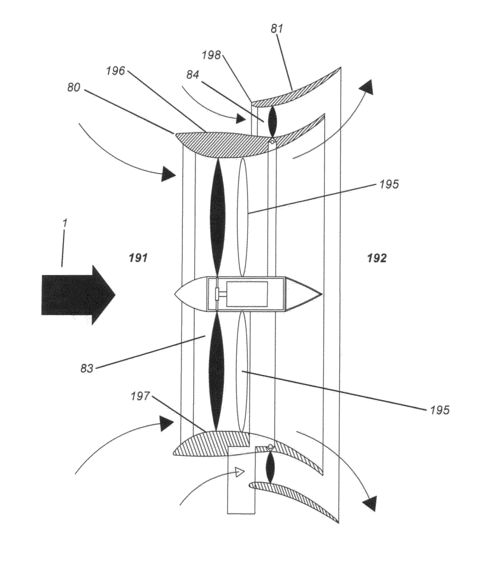
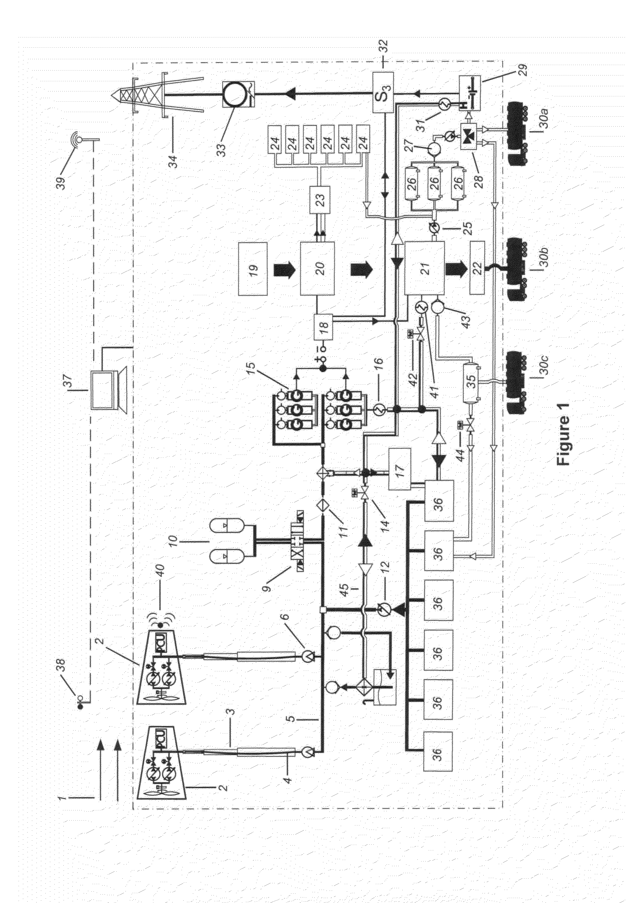
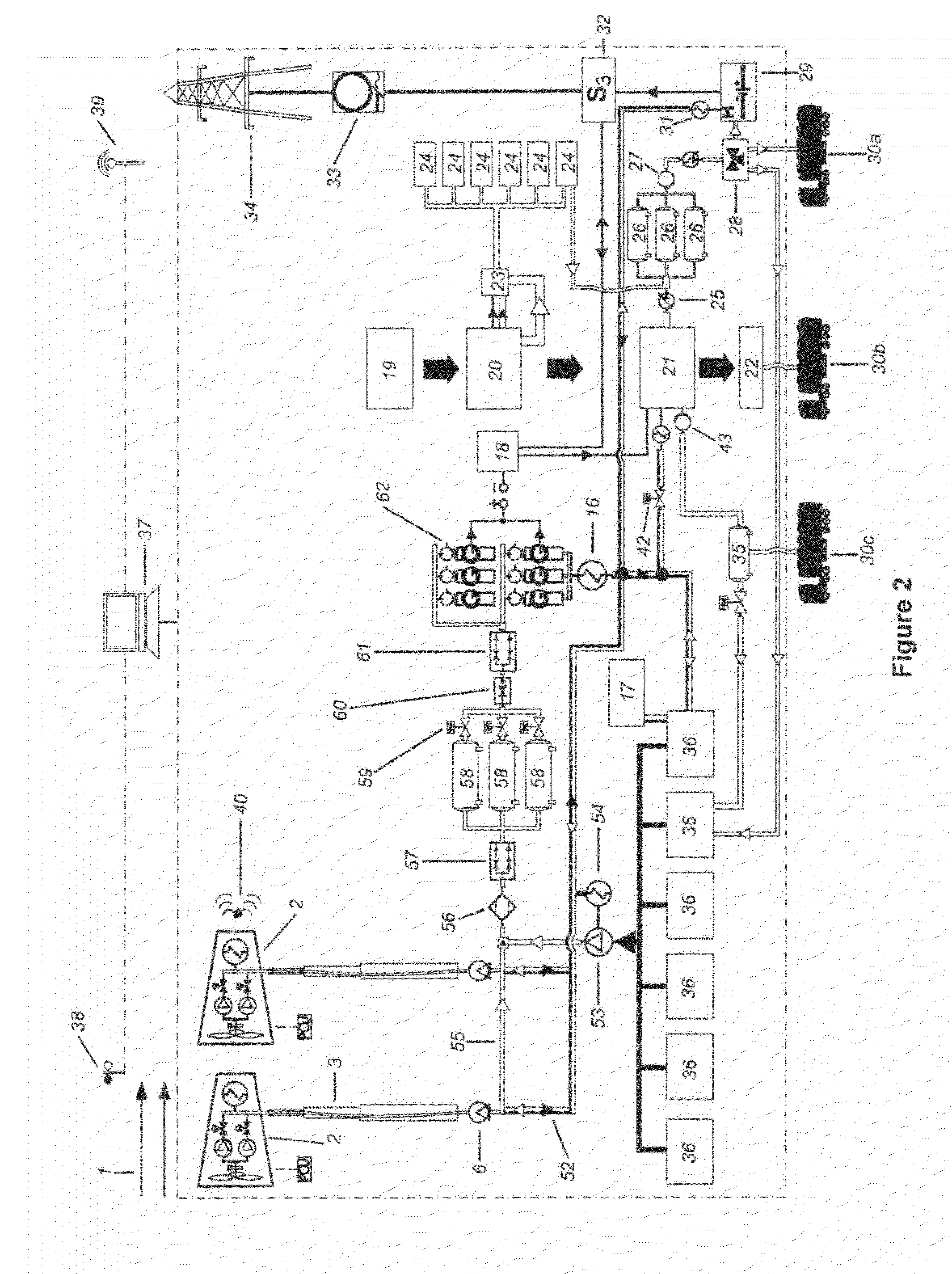
[0050]FIG. 1 is a schematic diagram of the wind energy system of the present invention. Specifically, FIG. 1 shows the process by which the sustainable energy system (SES) of the present invention extracts energy from wind through a decoupled multiple rotor ducted diffuser wind turbine by converting the energy from the prevailing wind into rotational energy of the rotor blades. The rotational energy captured by the rotor blades drives a series of hydraulic pumps that transfer the rotational energy into a pressurized fluid. The pressurized fluid transmits, balances and stores the captured energy in hydraulic accumulators, which retain the enemy under pressure that can then be released through valves in a controlled manner.

[0051]The fluid pressure is maintained in the accumulators by a membrane bladder (diaphragm), steel piston or steel bellows. Each of these options uses the hydraulic pressure to force the bladder, piston or bellows against an inert gas, which compresses under the pr...


PUM


Abstract

A wind energy system comprising a wind turbine comprising a cowling surrounded by a diffuser and a plurality of inner rotor blades located inside of the cowling that rotate about an inner hub, a plurality of outer rotor blades positioned between the diffuser and the cowling that are counter-rotating relative to the plurality of inner rotor blades, a drive mechanism located within the inner rotor hub, a dynamic telescopic tower, and a tower support that connects the wind turbine to the dynamic telescopic tower.

Description

CROSS-REFERENCE TO RELATED APPLICATION[0001]This application claims priority back to U.S. Patent Application No. 61 / 639,952 filed on Apr. 29, 2012.BACKGROUND OF THE INVENTION[0002]1. Field of the Invention[0003]The present invention relates generally to the field of wind energy, and more specifically, to a wind energy system and a method for using the wind energy system to store energy, mine metals, produce hydrogen and decontaminate water.[0004]2. Description of the Related Art[0005]The majority of the existing wind turbines use horizontal axis turbines. These turbines drive an electrical machine typically through a high ratio gearbox. The extracted power is processed fully, as in the case of permanent magnet generators, or partially by means of slip recovery, as in the case of doubly fed induction generators. In both cases, the electrical machine, associated gearbox, coupling and clutch are located in the nacelle on top of the tower. This has the consequence of requiring a larger ...

Claims


Application Information

Patent Timeline
IPC IPC(8): F03D1/04C25B1/02F03D9/02F03D11/02
CPCF03D1/0625F03D1/04F03D7/0204F05B2240/133F05B2240/13F05B2240/9151F05B2260/42F05B2260/404F05B2260/406F05B2260/4031Y02E10/728Y02E10/72F03D1/0658Y02P20/133F03D15/00F03D15/20F03D9/257F03D1/025F03D13/20F03D80/60F03D15/10
Inventor BLAKE, TIMOTHYRYTON, GEORGE HAROLDMANSIR, HASSANHEMINGWAY, NICHOLAS JAMES
Owner HFI IP HLDG LTD
Learn More