Time resolved laser raman spectroscopy using a single photon avalanche diode array

a laser raman spectroscopy and diode array technology, applied in the field of spectroscopy, can solve the problems of limiting the application of raman spectroscopy, interference from unwanted background fluorescence, size, cost and complexity of the apparatus

Inactive Publication Date: 2013-12-26
CALIFORNIA INST OF TECH
View PDF1 Cites 89 Cited by
  • Summary
  • Abstract
  • Description
  • Claims
  • Application Information

AI Technical Summary

Benefits of technology

[0012]According to one aspect, the invention features a time-gated spectroscopy apparatus. The time-gated spectroscopy apparatus comprises an illumination source configured to provide an optical excitation signal to excite a specimen of interest so as to generate an optical response signal; a trigger signal source configured to provide a trigger signal in synchrony with the optical excitation signal; a spectrometer configured to receive the optical response signal and to provide the optical response signal in a wavelength-dispersed format; a single photon avalanche diode array configured to receive the optical response signal in the wavelength-dispersed format, configured to trigger in response to the optical trigger signal, and configured to provide an electrical output signal representative of a time-gated portion of the optical response signal in the wavelength-dispersed format; a signal recorder configured to record the electrical output signal; and a controller configured to control the illumination source, the single photon avalanche diode array, and the signal recorder, and configured to provide the recorded electrical output signal in the form of a spectrum output.

Problems solved by technology

One issue that can limit the application of Raman spectroscopy is interference from unwanted background fluorescence, which is often much larger than the Raman signatures of interest.
Problems associated with using a streak camera include size, cost and complexity of the apparatus.

Method used


Image

  • Time resolved laser raman spectroscopy using a single photon avalanche diode array
  • Time resolved laser raman spectroscopy using a single photon avalanche diode array
  • Time resolved laser raman spectroscopy using a single photon avalanche diode array

Examples


Embodiment Construction

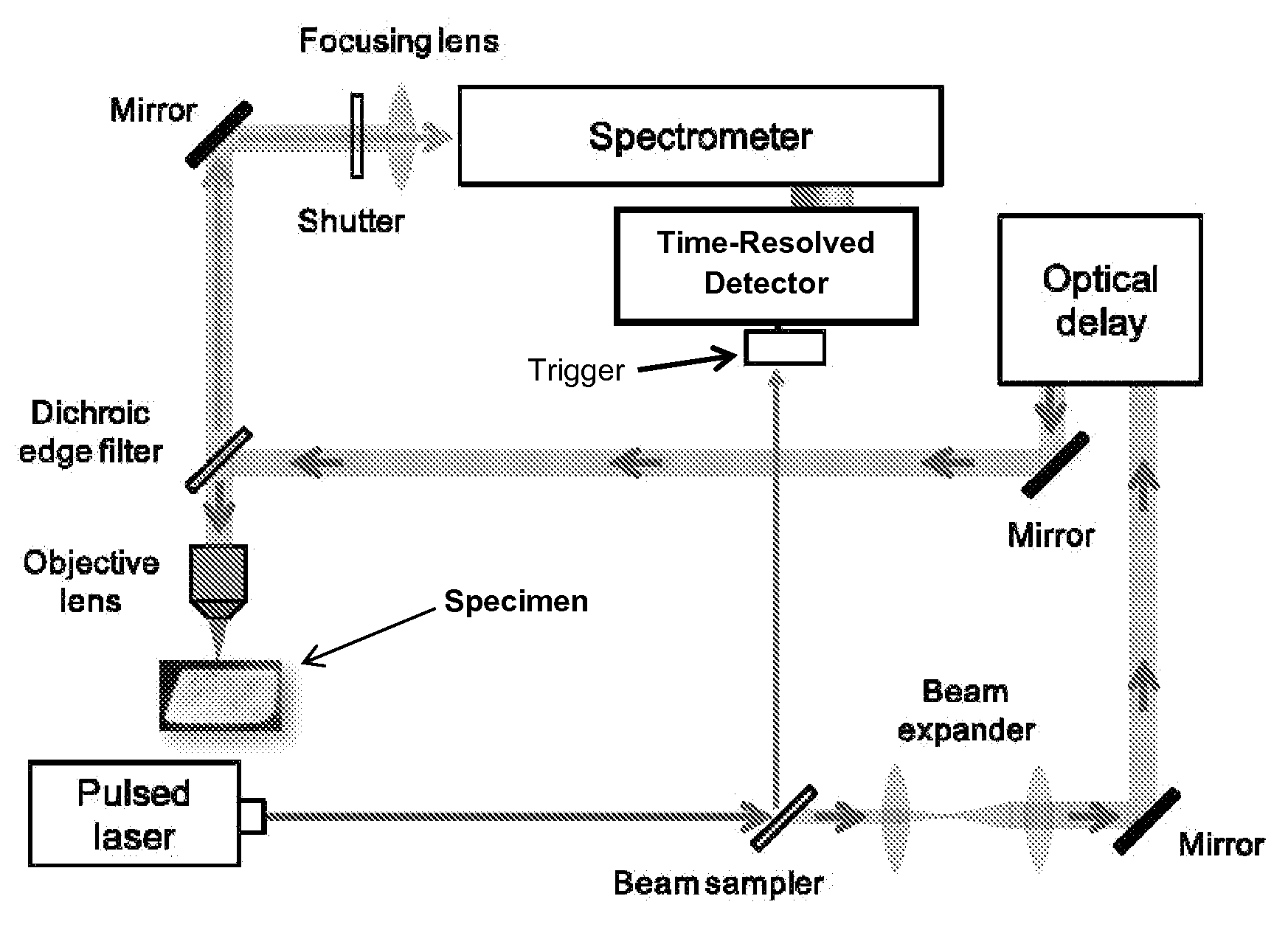
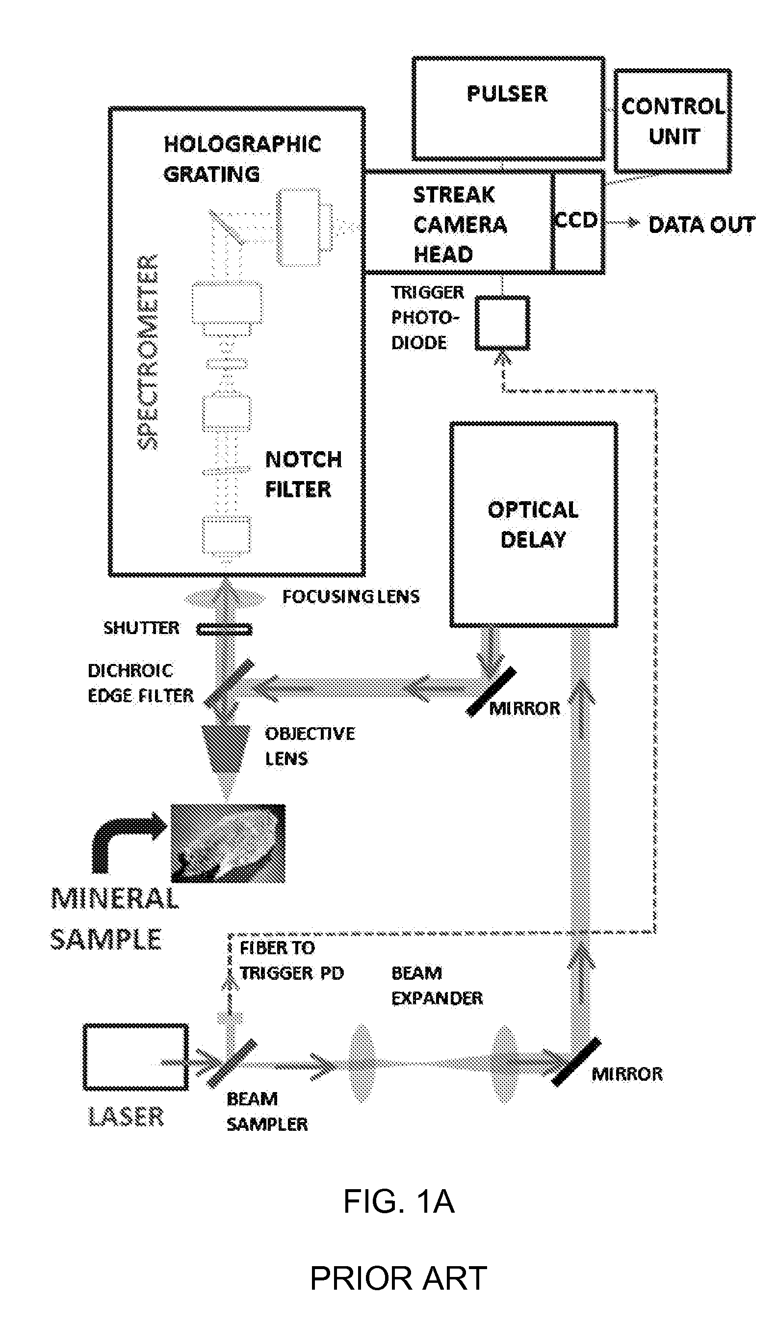
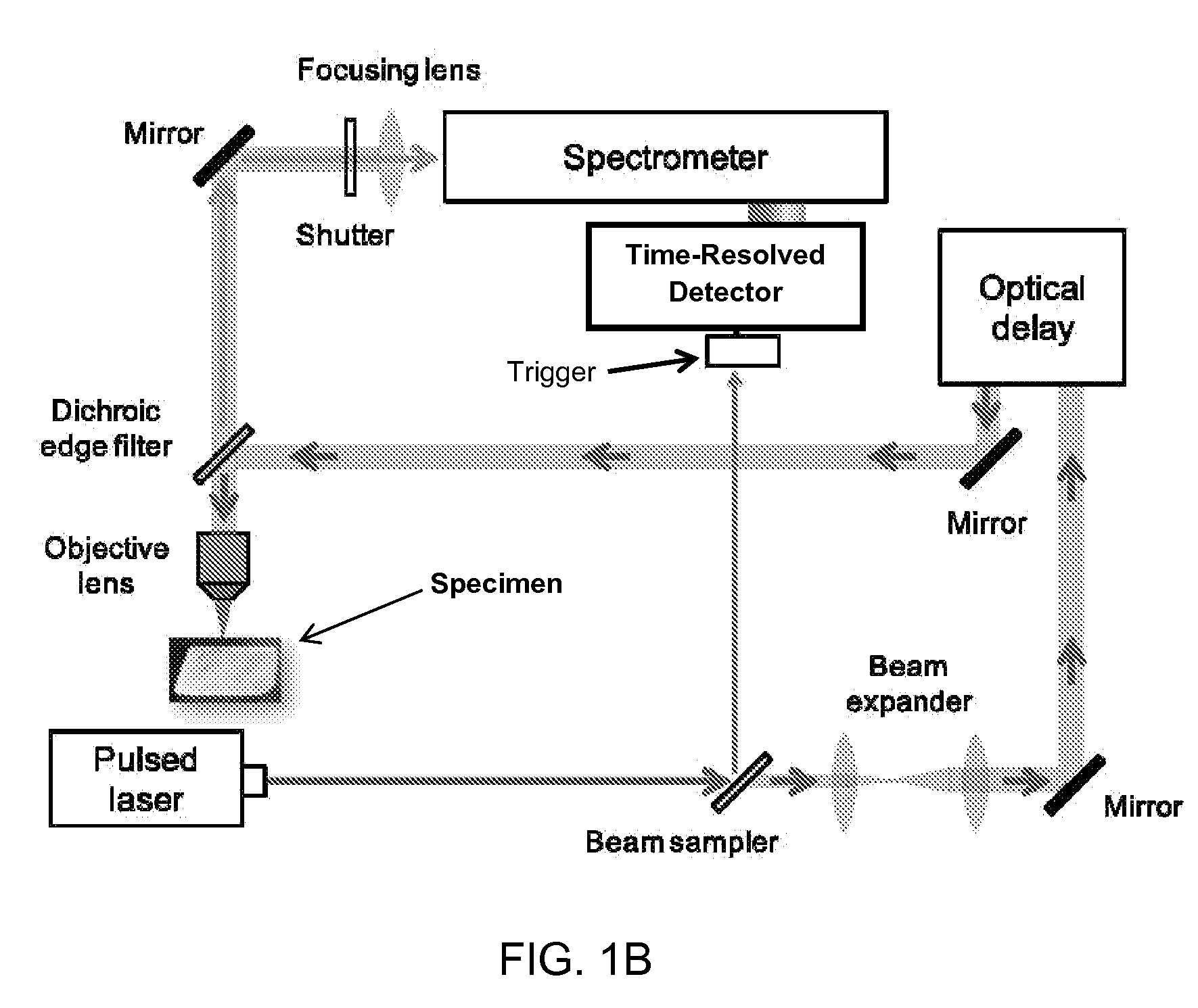
[0053]We have demonstrated that time-resolved Raman spectroscopy is now achievable using an all-solid-state 128×128 SPAD detector array as an alternative to a Raman spectrometer that uses a streak camera. Replacing the streak camera with a SPAD detector allows for lower power dissipation, lighter weight and reduced complexity. A solid state detector is also expected to be more robust than a streak camera which contains a sealed tube and high voltage electronics. It is also expected to be more radiation hard. We also demonstrate the achievement of laser induced breakdown spectroscopy (LIBS) in the same instrument. It is believed that a SPAD design can achieve improved sensitivity over the streak camera. The 128×128 SPAD array used has been described by Y. Maruyama and E. Charbon, in Proceedings of the Transducers 11 Conference (IEEE, 2011), p. 1180. The effective fill factor is 4.5%, and a microlens array is used with a concentration factor of 1.59. Though not ideally designed for Ra...


PUM


Abstract

A Raman spectrometer that employs a time-gated single photon avalanche diode array as a sensor is described. The spectrometer can also perform fluorescence spectroscopy and laser induced breakdown spectroscopy (LIBS). A laser is used to provide an excitation signal to excite a specimen of interest. A spectrometer is used to separate the various intensities over a range of wavelengths, which are then caused to impinge on the array to be recorded. The time-gated single photon avalanche diode array is triggered in synchrony with the excitation signal so as to allow time resolution of the response of the sample of interest to the excitation. The array can be time-gated to resolve signals that have shorter durations as a function of time while excluding signals that have a longer time duration. Raman and LIBS signals can be observed even from specimens that fluoresce strongly.

Description

CROSS-REFERENCE TO RELATED APPLICATIONS[0001]This application claims priority to and the benefit of co-pending U.S. provisional patent application Ser. No. 61 / 663,948 filed Jun. 25, 2012, which application is incorporated herein by reference in its entirety.STATEMENT REGARDING FEDERALLY FUNDED RESEARCH OR DEVELOPMENT[0002]The invention described herein was made in the performance of work under a NASA contract, and is subject to the provisions of Public Law 96-517 (35 USC 202) in which the Contractor has elected to retain title.THE NAMES OF THE PARTIES TO A JOINT RESEARCH AGREEMENT[0003]NOT APPLICABLE.INCORPORATION-BY-REFERENCE OF MATERIAL SUBMITTED ON A COMPACT DISC[0004]NOT APPLICABLE.FIELD OF THE INVENTION[0005]The invention relates to spectroscopy in general and particularly to systems and methods that provide Raman spectra and laser-induced breakdown spectra (LIBS).BACKGROUND OF THE INVENTION[0006]Since its discovery more than 80 years ago, and elevation 30 years later with the ...

Claims


Application Information

Patent Timeline
Patent Type & Authority Applications(United States)
IPC IPC(8): G01J3/28G01J3/44
CPCG01J3/2803G01J3/44G01J3/2889
Inventor BLACKSBERG, JORDANA
Owner CALIFORNIA INST OF TECH
Why Eureka
Try Eureka