Self-Heating Patch

a self-heating patch and patch technology, applied in the field of self-heating patches, can solve the problems of difficult control, light skin patches, difficult to use as relatively thin,

Inactive Publication Date: 2013-12-26
SEALED AIR U S
View PDF0 Cites 45 Cited by
  • Summary
  • Abstract
  • Description
  • Claims
  • Application Information

AI Technical Summary

Problems solved by technology

They are unfortunately not amenable to use as relatively thin, lightweight skin patches.
These produce steam, however, and must be vented.
Further, they are difficult to control and may be subject to over-heating in skin-contact applications.
However, the phase change material is not itself a heat generator unless pre-heated by some other means.
Also, such heaters tend to be bulky and heavy.
Further, use of a ...

Method used


Image

  • Self-Heating Patch
  • Self-Heating Patch
  • Self-Heating Patch

Examples


example 1

[0209]A Gurley Densitometer, Model 4150N equipped with a 4320 Automatic Digital Timer, was used to characterize the relative permeation rate of film samples. Pressure was 6.52 psi, sample area was 1 sq. in., and displacement volume was 10 cc. This test method measures the time for a known air volume to pass through a porous film sample under a known air pressure gradient. A longer time value thus indicates a lower permeation rate.

[0210]Table 4 below shows the results obtained:

TABLE 4Air permeation measurements on film samplesFilm SampleGurley ReadingDesignationFilm Sample Description(seconds + / − std. dev.)1FS-1, as made22.4 + / − 0.52FS-1, after heating @22.7 + / − 0.2140° F. for 1 minute3FS-1, after heating @65.8 + / − 0.5275° F. for 1-2 minutes4FS-1, after heating @245 + / − 3 275° F. for 1-2 minutes, then @282° F. for 1-2 minutes5FS-2, as made42.3 + / − 4.16FS-2, after heating @994 (single reading)140° F. for 1 minute7FS-3, as made 51.4 + / − 13.18FS-4, as made122 + / − 16

[0211]The results of ...

example 2

[0213]An Omega Model HH309A four-channel data logger thermometer was used for collection of time-temperature measurements from the surface of test patches constructed using Sample FS-1 to Sample FS-4 films, as described below.

[0214]The general procedure for making test patches was to affix a piece of 3″ wide clear packaging tape to the face of a flat rectangular metal frame having a 2″×6″ opening and made from ⅛″ aluminum. Inside a nitrogen-filled glove box, an approximately 1″×2″ test strip of self-heating material was removed from a COOKPAK heater. This sheet, about 1 / 16″ thick, was affixed to the tape surface centered inside the metal frame so as to leave at least ½″ open margin around all sides. One or two microporous film samples was / were laid over this heating material, waxed side up (where applicable) so as to extend at least ½″ beyond the self-heating material edges. The film sample was press-adhered to the tape surface so as to form a seal around all edges. In some cases a ...

example 3

Prophetic Example

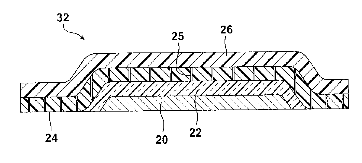
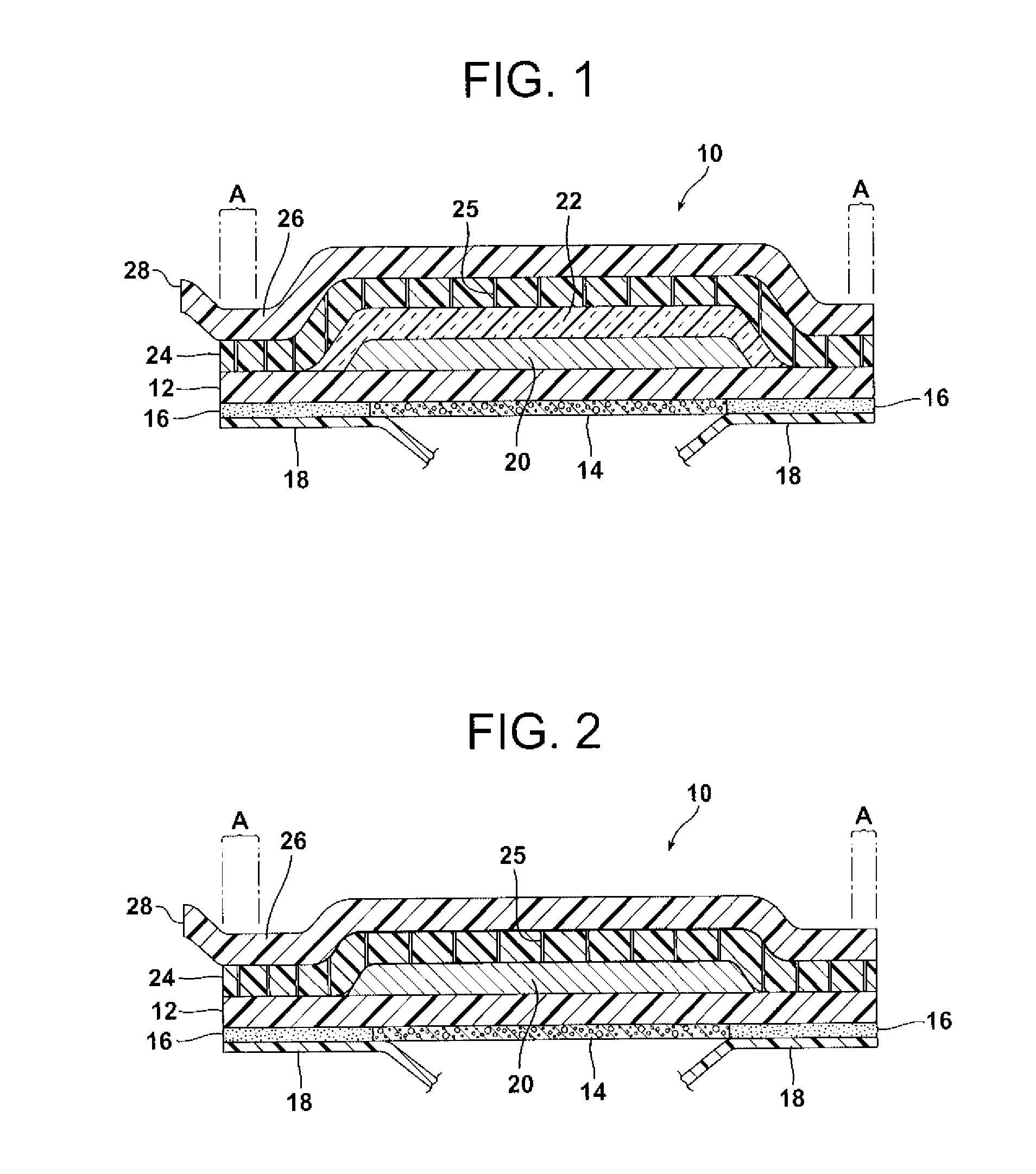
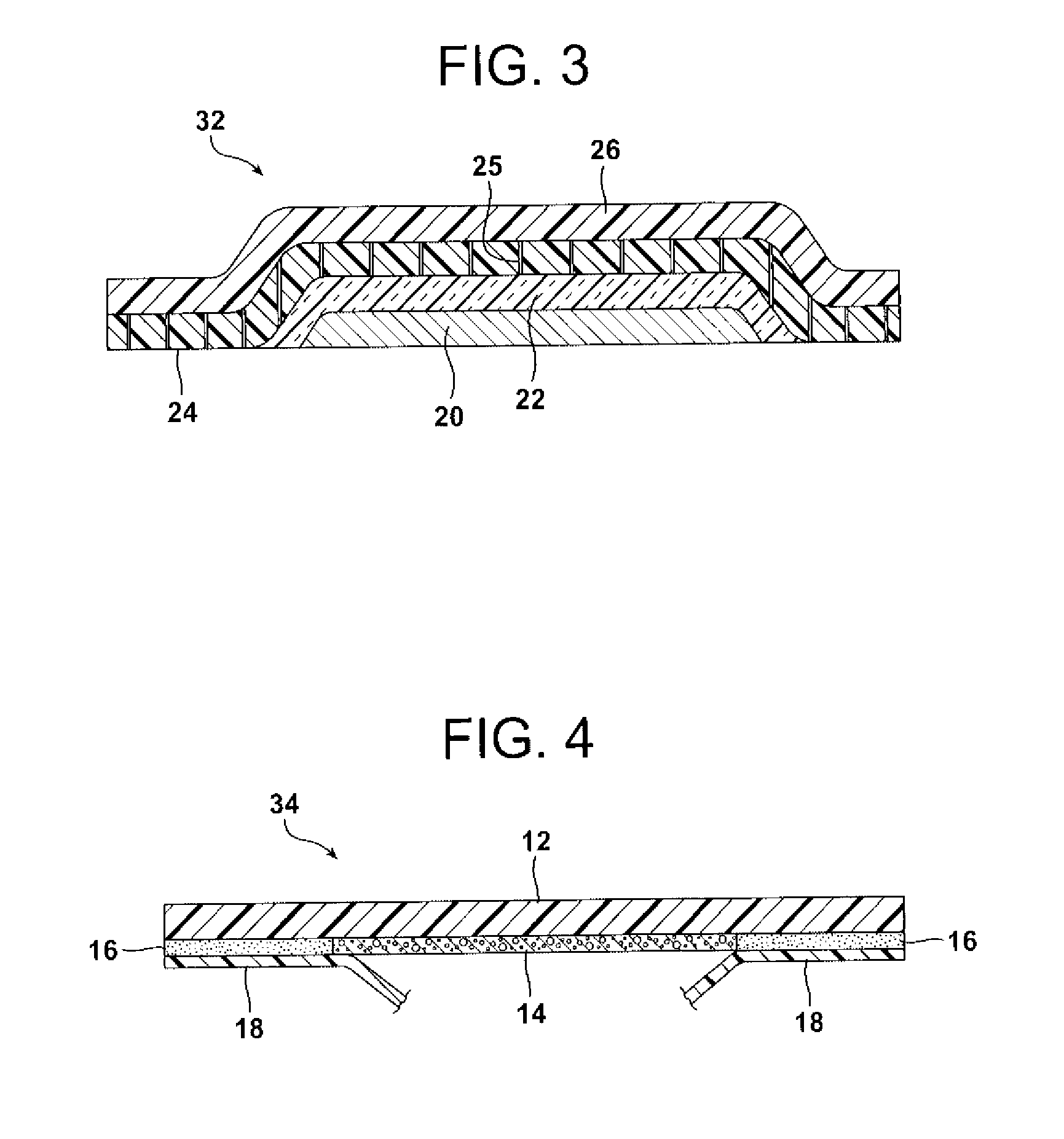
[0220]A perimeter-sealed self heating patch is constructed from a self heating layer, a top film layer and a bottom film layer, where the self heating layer does not extend to the edges and is sealed between the top and bottom film layers, which come into contact around the edges.

[0221]The layers are defined further as follows:

[0222]Top Film Layer

[0223]A continuous microporous flexible film having average pore size of less than 10 microns, e.g. less than 1 micron, and an air permeation rate that leads to a time of less than about 2000 seconds, and greater than about 200 seconds, when the film is tested in a Gurley tester at 6.52 psi, 10 cc displacement, 1 sq. inch area.

[0224]In one embodiment, this film is made from a heat-treated composite microporous film having core layer and skin layers, where the core layer has a lower melting temperature range than the skin layers and the heat treatment is within the melting temperature range of the core layer. In another embo...


PUM

PropertyMeasurementUnit
Temperatureaaaaaaaaaa
Flexibilityaaaaaaaaaa
Adhesivityaaaaaaaaaa

Abstract

A self-heating patch includes a bottom barrier layer, an air-activated heat-generating layer, an air regulation layer, optionally a top barrier layer, and optionally a skin contact layer, wherein the air-activated heat-generating layer is encapsulated by the air regulation layer and bottom barrier layer, and/or the top and bottom barrier layers, and the temperature of the patch, when the air-activated heat-generating layer has been exposed to air, and when the top barrier layer if present is removed, is controlled at least in part by the air regulation layer; and a perimeter seal seals the air regulation layer to the bottom barrier layer around the perimeter of the patch. Optionally a temperature-responsive mechanism, such as a wax, can be used to reduce oxygen intake into the self-heating patch and thereby control the temperature of the self-heating patch during use. Optionally, a portion of the self-heating patch can be thermoformed.

Description

[0001]This application claims the benefit of U.S. Provisional Application No. 61 / 664,323 filed Jun. 26, 2012, and U.S. Provisional Application No. 61 / 697,337 filed Sep. 6, 2012, these applications incorporated herein by reference in their entirety.FIELD OF THE INVENTION[0002]This invention relates to a self-heating patch, and to a method of making the self-heating patch.BACKGROUND OF THE INVENTION[0003]Dermal patches, such as back warmers, face masks, hand warmers, and thermal wraps for placement on the body to heat muscles, are typically made with air activated exothermic reactive materials, such as salt-activated iron powders, that achieve temperature regulation by means of a formulation having a low energy density and reaction rate, such that their own heat capacity and reaction rate limitations serve to regulate the temperature rise. They are unfortunately not amenable to use as relatively thin, lightweight skin patches.[0004]Other currently available heat generating sachets emp...

Claims


Application Information

Patent Timeline
IPC IPC(8): A61F7/03A61K9/70
CPCA61F7/034A61K9/7084A61F2007/0098A61F2007/0261Y10T156/1002Y10T156/1052
Inventor STOCKLEY, III, HENRY WALKERROBERTS, WILLIAM PEYTONCOMPTON, STEPHEN F.SPEER, DREW VE
Owner SEALED AIR U S
Why Eureka
Try Eureka