Vibratory gyroscope

a vibrating gyroscope and vibration technology, applied in the direction of turning-sensitive devices, acceleration measurement using interia forces, instruments, etc., can solve the problems of increased size, low signal-to-noise ratio, and inability to continuously rotate the primary motion, so as to improve the signal level output and improve the effect of signal level

Active Publication Date: 2014-01-02
MURATA MFG CO LTD
View PDF5 Cites 22 Cited by
  • Summary
  • Abstract
  • Description
  • Claims
  • Application Information

AI Technical Summary

Benefits of technology

[0008]The present invention is based on the idea of applying the resonance gain by letting the primary and the secondary frequencies to coincide to improve the signal levels output from the second...

Problems solved by technology

In MEMS gyros the primary motion cannot be continuous rotation as in conventional ones due to a lack of adequate bearings.
The generated signal may be amplified electrically, bu...

Method used


Image

  • Vibratory gyroscope
  • Vibratory gyroscope
  • Vibratory gyroscope

Examples


Embodiment Construction

[0021]The following embodiments are exemplary. Although the specification may refer to “an”, “one”, or “some” embodiment(s), this does not necessarily mean that each such reference is to the same embodiment(s), or that the feature only applies to a single embodiment. Single features of different embodiments may be combined to provide further embodiments.

[0022]In the following, features of the invention will be described with a simple example of a device architecture in which various embodiments of the invention may be implemented. Only elements relevant for illustrating the embodiments are described in detail. Various implementations of sensor devices and methods that are generally known to a person skilled in the art may not be specifically described herein.

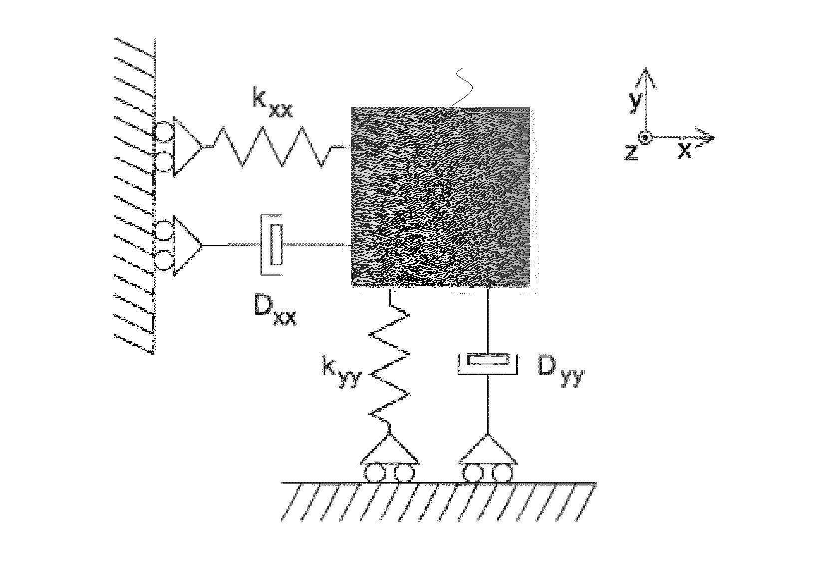
[0023]To establish the applied concepts and terms, FIG. 1 shows a diagram of a prior art 2-degree-of-freedom (DoF) mechanical resonator, as depicted in prior art (for example: “System and circuit design for a capacitive MEMS gyr...


PUM

PropertyMeasurementUnit
Fractionaaaaaaaaaa
Areaaaaaaaaaaa
Frequencyaaaaaaaaaa

Abstract

A sensing device comprising a micromechanical gyroscope, the gyroscope comprising an improved sensing device with a micromechanical gyroscope, where the resonance frequency of the first mechanical resonator and the resonance frequency of the second mechanical resonator are adjusted to essentially coincide. The device comprises a feed-back loop connected to the second mechanical resonator, the quality factor of the combination of the feed-back loop and the second mechanical resonator being less than 10. More accurate sensing is achieved without essentially adding complexity to the sensor device configuration.

Description

FIELD OF THE INVENTION[0001]The present invention relates to microelectromechanical devices and especially to a sensor device and a method for sensing angular velocity, as defined in the preambles of the independent claims.BACKGROUND OF THE INVENTION[0002]Micro-Electro-Mechanical Systems, or MEMS can be defined as miniaturized mechanical and electro-mechanical systems where at least some elements have some mechanical functionality. Since MEMS devices are created with the same tools used to create integrated circuits, micromachines and microelectronics can be fabricated on the same piece of silicon to enable machines with intelligence.[0003]MEMS structures can be applied to quickly and accurately detect very small changes in physical properties. For example, a microelectromechanical gyroscope can be applied to quickly and accurately detect very small angular displacements. Motion has six degrees of freedom: translations in three orthogonal directions and rotations around three orthog...

Claims


Application Information

Patent Timeline
IPC IPC(8): G01C19/56G01C25/00
CPCG01C19/56G01C25/00G01C19/5726G01C19/5762G01C19/5776Y10T29/49002B81B7/008
Inventor BLOMQVIST, ANSSI
Owner MURATA MFG CO LTD
Why Eureka
Try Eureka