Methods and apparatuses for thermally converting biomass

a technology of thermal conversion and biomass, applied in the direction of biofuels, biofuels, products, etc., can solve the problems of reducing the yield of pyrolysis oil proportionally to the amount of oxygen added, and typical thermal conversion units exhibit up to about 2% liquid yield loss

Active Publication Date: 2014-01-02
ENSYN RENEWABLES
View PDF9 Cites 41 Cited by
  • Summary
  • Abstract
  • Description
  • Claims
  • Application Information

AI Technical Summary

Benefits of technology

[0007]In accordance with another exemplary embodiment, a method for thermally converting biomass includes delivering the biomass to a thermal conversion reactor and introducing a carrier gas having a selected oxygen content to the thermal conversion reactor. The carrier gas carries the biomass through the thermal conversion reactor. The method includes thermally converting the biomass in the thermal conversion reactor and inhibiting the introduction of additional oxygen to the thermal conversion reactor.
[0008]In accordance with another exemplary embodiment, an apparatus for thermally converting biomass includes a reactor feed chamber for holding the biomass. The apparatus further includes a thermal conversion reactor configured to thermally convert the biomass and in communication with the reactor feed chamber for receiving the biomass. An instrument is provided in communication with the thermal conversion reactor and is adapted to monitor conditions in the thermal conversion reactor. Further, the apparatus includes a purge line in communication with the reactor feed chamber and the instrument and adapted to flow low oxygen gas into the reactor feed chamber and into the instrument to inhibit the introduction of oxygen into the thermal conversion reactor.

Problems solved by technology

However, the introduction of additional oxygen through the biomass inlet and instrument purge inlets reduces the pyrolysis oil yield proportionally to the amount of oxygen added.
As a result, a typical thermal conversion unit exhibits up to about a 2% liquid yield loss due to the ingress of additional oxygen into the thermal conversion reactor.

Method used


Image

  • Methods and apparatuses for thermally converting biomass
  • Methods and apparatuses for thermally converting biomass
  • Methods and apparatuses for thermally converting biomass

Examples


Embodiment Construction

[0016]The following detailed description is merely exemplary in nature and is not intended to limit the methods and apparatuses for thermally converting biomass. Furthermore, there is no intention to be bound by any expressed or implied theory presented in the preceding technical field, background or brief summary, or in the following detailed description.

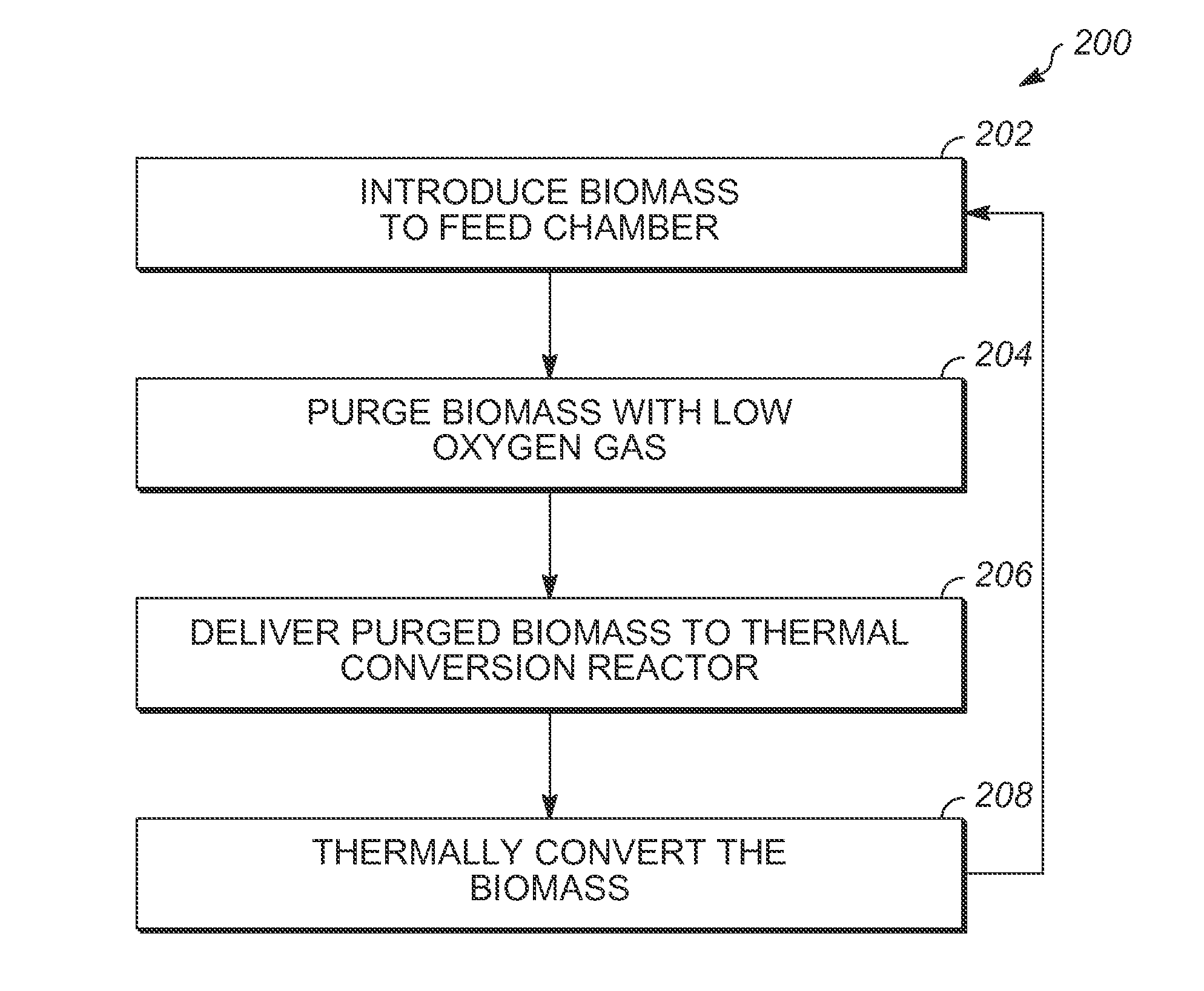
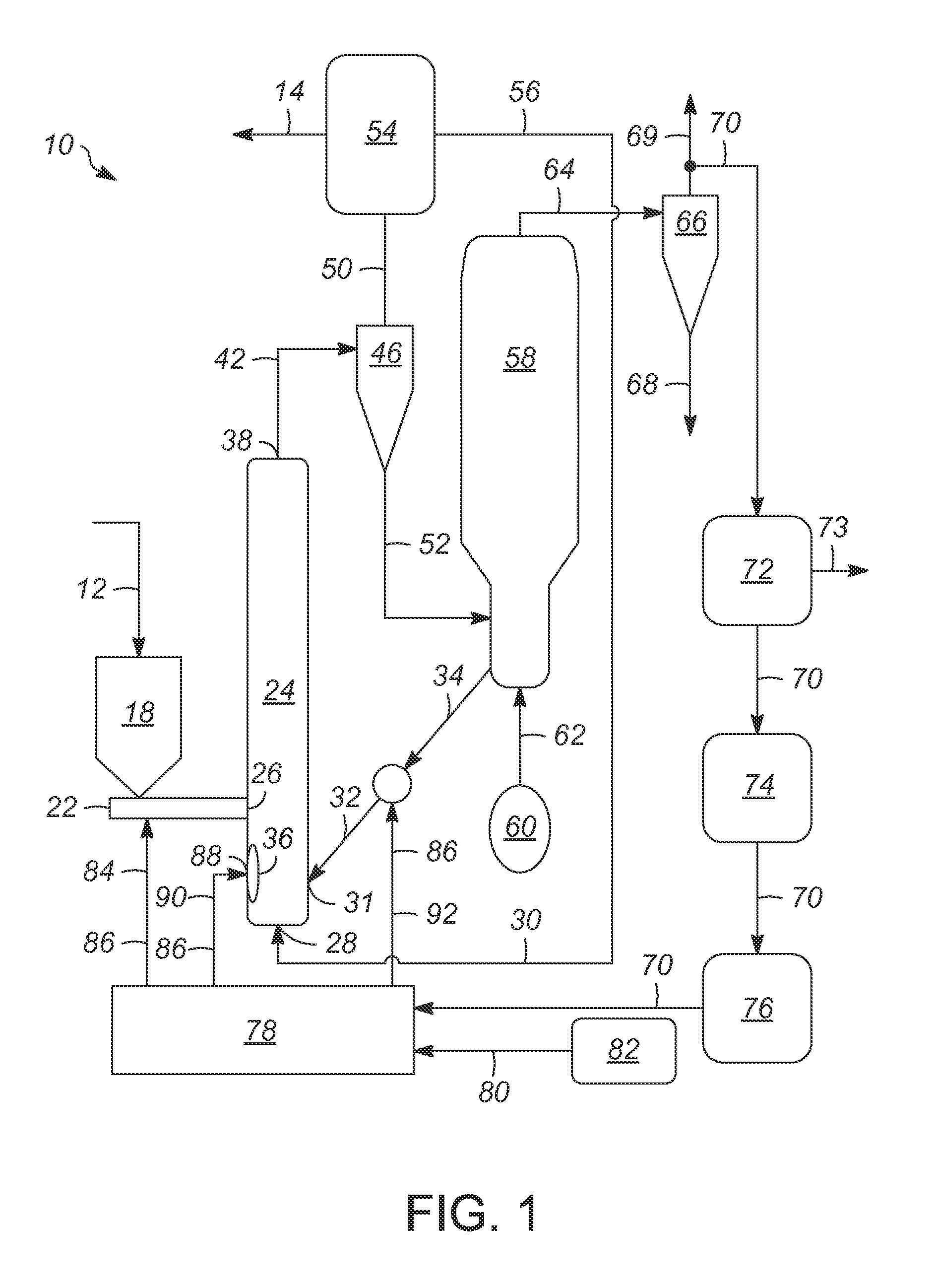
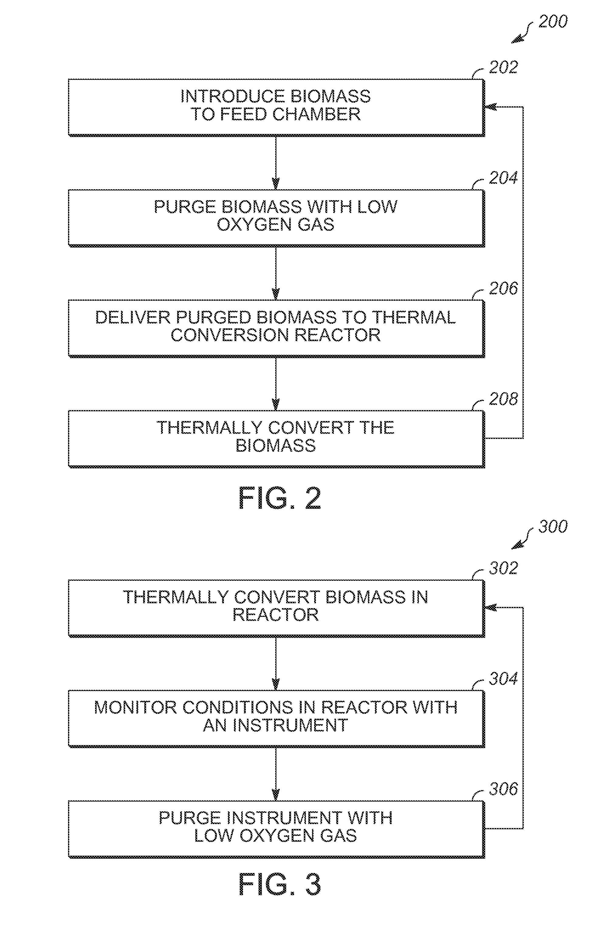
[0017]It is contemplated herein that the thermal conversion of biomass can be improved under conditions in which oxygen levels are controlled at selected levels. Specifically, the methods and apparatuses for thermally converting biomass described herein can be used to limit the volume of oxygen introduced to a thermal conversion reactor. Conventional thermal conversion processes utilize a carrier gas having a desired oxygen level, such as no more than about 5 vol %, which enters the thermal conversion reactor and carries the biomass through the thermal conversion reactor during the thermal conversion reaction. However, in the conve...


PUM

PropertyMeasurementUnit
pressureaaaaaaaaaa
temperaturesaaaaaaaaaa
temperatureaaaaaaaaaa

Abstract

Methods and apparatuses for thermally converting or pyrolyzing biomass are provided. In one embodiment, a method of thermally converting biomass includes introducing the biomass to a reactor feed chamber. The method provides for flowing a low oxygen gas into the reactor feed chamber to purge the reactor feed chamber and biomass of oxygen. The method also includes delivering the purged biomass to a thermal conversion reactor and thermally converting the biomass in the thermal conversion reactor.

Description

TECHNICAL FIELD[0001]The present invention generally relates to methods and apparatuses for thermally converting, or pyrolyzing, biomass and more particularly relates to methods and apparatuses for thermally converting biomass that operate at controlled oxygen levels.BACKGROUND[0002]Renewable energy sources are of increasing importance. They are a means of reducing dependence on oil and they provide a substitute for other fossil fuels. Also, renewable energy resources can provide for basic chemical constituents to be used in other industries, such as chemical monomers for the making of plastics. Biomass is a renewable resource that can supply some of the need for renewables-based chemicals and fuels.[0003]Biomass includes, but is not limited to, lignin, plant parts, fruits, vegetables, plant processing waste, wood chips, chaff, grains, grasses, corn and corn husks, weeds, aquatic plants, hay, recycled and non-recycled paper and paper products, and any cellulose-containing biological...

Claims


Application Information

Patent Timeline
Patent Type & Authority Applications(United States)
IPC IPC(8): C10B43/00
CPCC10B49/10C10B49/22C10B53/02Y02E50/10Y02P20/145C10B49/00C10B49/16C10B49/20
Inventor BAIRD, LANCE AWENDERFREEL, BARRYCLARKE, DOUGMORIN, GREGORY JOSEPH
Owner ENSYN RENEWABLES
Why Eureka
Try Eureka