Delay locked loop with a loop-embedded duty cycle corrector

a duty cycle corrector and delay lock technology, applied in the direction of pulse automatic control, pulse manipulation, pulse technique, etc., can solve the problems of frequent deviation of the duty cycle of the clock signal from 50%, clock skew inevitably occurring, circuit or system malfunction, etc., to reduce power consumption and chip area

Active Publication Date: 2014-01-02
SK HYNIX INC +1
View PDF17 Cites 26 Cited by
  • Summary
  • Abstract
  • Description
  • Claims
  • Application Information

AI Technical Summary

Benefits of technology

[0009]Accordingly, embodiments of the present invention has been made in an effort to solve the problems occurring in the related art, and an advantage of an embodiment of the present invention is to provide a delayed locked loop (DLL) including a duty cycle corrector embedded therein, which is capable of reducing power consumption and chip area.

Problems solved by technology

When an external clock signal is inputted to a circuit or system, a clock skew inevitably occurs.
Thus, a duty cycle of the clock signal may frequently deviate from 50%.
The deviation may cause malfunction in the circuit or system such as a DDR system that operates based on rising and falling edges of the clock signal.
However, the addition of the DCC may cause other problems.
As a result, a maximum operating frequency of the input clock signal RefCLK inputted to the DLL may be limited by this phenomenon.

Method used


Image

  • Delay locked loop with a loop-embedded duty cycle corrector
  • Delay locked loop with a loop-embedded duty cycle corrector
  • Delay locked loop with a loop-embedded duty cycle corrector

Examples


Embodiment Construction

[0032]Reference will now be made in greater detail to a preferred embodiment of the invention, an example of which is illustrated in the accompanying drawings. Wherever possible, the same reference numerals will be used throughout the drawings and the description to refer to the same or like parts.

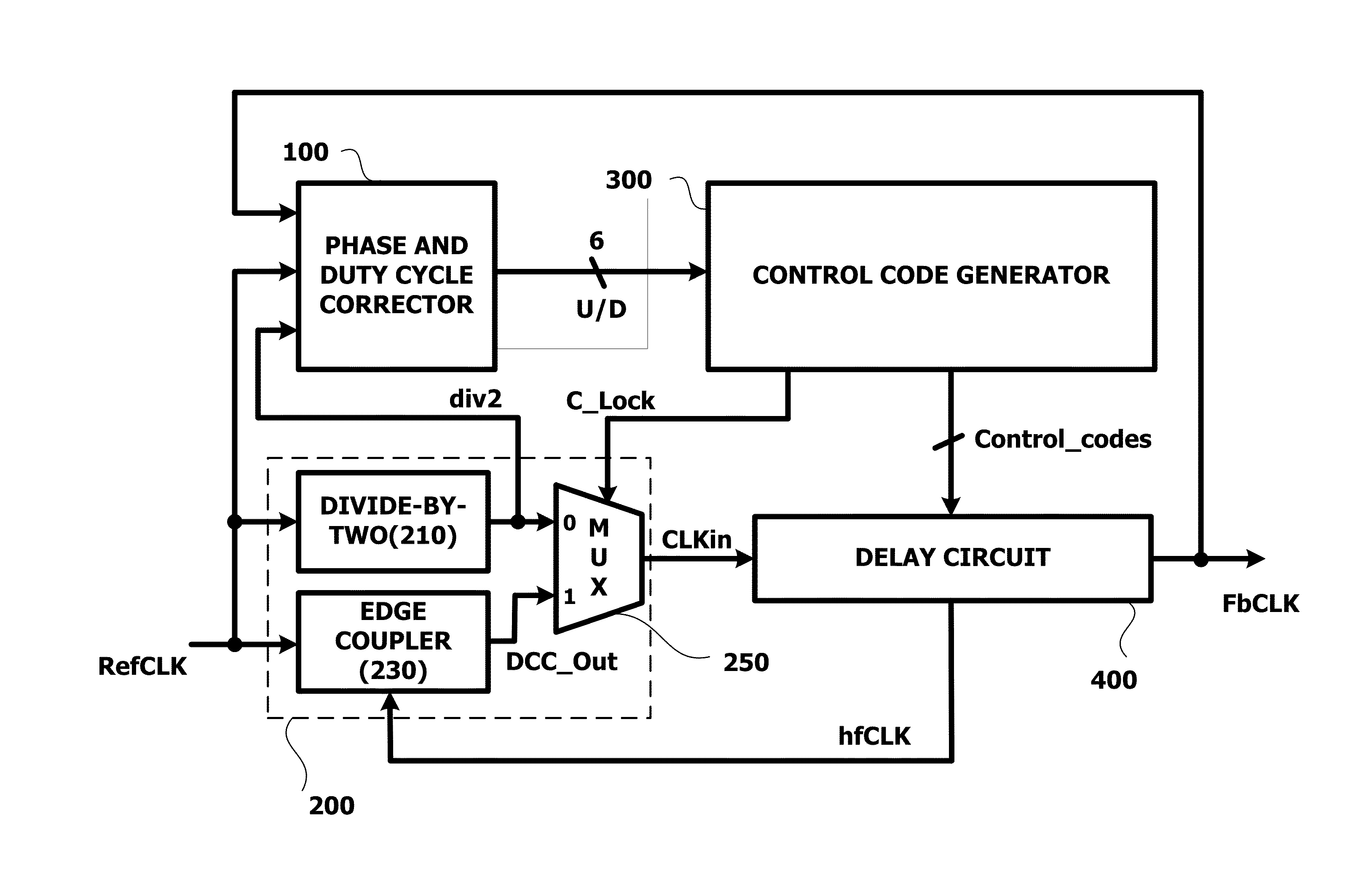
[0033]FIG. 3 illustrates a block diagram of a DLL according to an embodiment of the present invention.

[0034]Referring to FIG. 3, the DLL receives an input clock signal RefCLK and generates an output clock signal FbCLK of which a duty cycle is corrected to 50%. The DLL includes a phase and duty cycle detector 100, a duty cycle corrector 200, a control code generator 300, and a delay circuit 400.

[0035]The duty cycle corrector 200 is configured to receive the input clock signal RefCLK and output a clock signal CLKin of which a duty cycle corresponds to about 50%. For this operation, the duty cycle corrector 200 includes a divide-by-two circuit 210, an edge coupler 230, and a multiplexer (MUX)...


PUM


Abstract

A delayed locked loop (DLL) adjusts a duty cycle of an input clock signal and outputs an output clock signal. The DLL includes a phase and duty cycle detector configured to detect a phase and duty cycle of the input clock signal, a duty cycle corrector configured to correct the duty cycle, a control code generator configured to detect coarse lock of the DLL and generate a binary control code corresponding to the detection result, and a delay circuit configured to delay an output signal of the duty cycle corrector by a predetermined time according to the binary control code, tune the duty cycle thereof, and mix the phase thereof, wherein the phase and duty cycle detector, the duty cycle corrector, the control code generator, and the delay circuit form a feedback loop.

Description

CROSS-REFERENCES TO RELATED APPLICATION[0001]The present application claims priority to Korean patent application number 10-2012-0071347, filed on Jun. 29, 2012, which is incorporated by reference herein in its entirety.BACKGROUND OF THE INVENTION[0002]1. Field of the Invention[0003]Embodiments of the present invention relates to a delay locked loop (DLL), and more particularly, to a DLL that includes a duty cycle corrector to correct a duty cycle of a DLL output signal and controls one delay circuit to be commonly used in a duty cycle correction operation and a locking operation of the DLL.[0004]2. Description of the Related Art[0005]In semiconductor circuit technology, a clock signal is used as a reference signal for adjusting operational timing in a system or circuit. When an external clock signal is inputted to a circuit or system, a clock skew inevitably occurs. Such a clock skew is typically corrected to generate an internal clock signal having the same phase as the external c...

Claims


Application Information

Patent Timeline
Patent Type & Authority Applications(United States)
IPC IPC(8): H03L7/08
CPCH03L7/0802H03K5/131H03L7/0814H03L7/0818H03L7/087H03L7/10H03K5/156H03L7/081
Inventor PARK, HONG JUNELIM, JI HUN
Owner SK HYNIX INC
Why Eureka
Try Eureka