Methods and systems for producing an implant

a technology of implants and production methods, applied in the field of implants to replace bony structures, can solve the problems of limited relevance of their methods and implants to the relevant field, ineffective and time-consuming segmentation techniques, and computationally expensive detection of anatomical surfaces as complex as the skull or soft tissue face with prior information alone, so as to save time

Inactive Publication Date: 2014-01-02
OSTEOPLASTICS
View PDF4 Cites 43 Cited by
  • Summary
  • Abstract
  • Description
  • Claims
  • Application Information

AI Technical Summary

Benefits of technology

[0035]One advantage of the present invention is that it presents an unsupervised neural network algorithm (i.e., self organizing feature map, or SOFM) for automated and accurate 3D surface segmentation, the latter being a necessity for computer generation of cranial implants, diagnostic cephalometrics and image guided surgery.
[0036]Another advantage of the present invention is that user interaction in the SOFM algorithm is limited to determining which segmented surfaces represent the anatomy desired by the user.
[0037]Another advantage of the present invention is that it rapidly assembles automatically segmented, and anatomically valid (i.e., no correction required), surfaces into a surface of interest for rendering of 3D surfaces found in volume images.
[0038]Another advantage of the present invention is that it saves time over manually identifying each pixel or currently available semi-automatic methods.
[0039]Another advantage of the present invention is that it locates continuous surfaces, even in areas of thin structure or imaging artifact (e.g., metallic artifact in x-ray or CT).
[0040]Another advantage of the present invention is that it combines spatial and intensity information to track 3D surfaces for segmentation.

Problems solved by technology

Each of these patents, however, suffer from many disadvantages that have collectively limited the usefulness of their methods and implants to the relevant field.
Although clinical visualization of three dimensional organ surfaces embedded in an imaged volume is now common, segmentation techniques are often ineffective and time consuming.
However, detection of anatomical surfaces as complex as the skull or soft tissue face with prior information alone is computationally expensive.
It is likely manual work will be necessary where the signal is too low, especially in regions with high artifact noise or where artifact-interrupted surface morphology may obfuscate a match with database information.
Current slice-based segmentation methods tend to be time consuming.
Difficulty in making segmentation decisions based on these three (3) types of information may be compounded by a user environment where an image volume is presented as a series of tomographic or projection images that lose resolution when reformatted.
Deformable curve fitting for edge detection seems less adaptable than manual segmentation for determining the location of anatomical edges.
Curve fitting runs into trouble when edges vary in signal strength, requiring multiple initialization and guidance steps to obtain best-fit.
However, these simple models are less adaptable, or less decisive, than manual segmentation.
However, estimating the shape of a defect of large size with an average of too few subjects is also not helpful.

Method used


Image

  • Methods and systems for producing an implant
  • Methods and systems for producing an implant
  • Methods and systems for producing an implant

Examples


Embodiment Construction

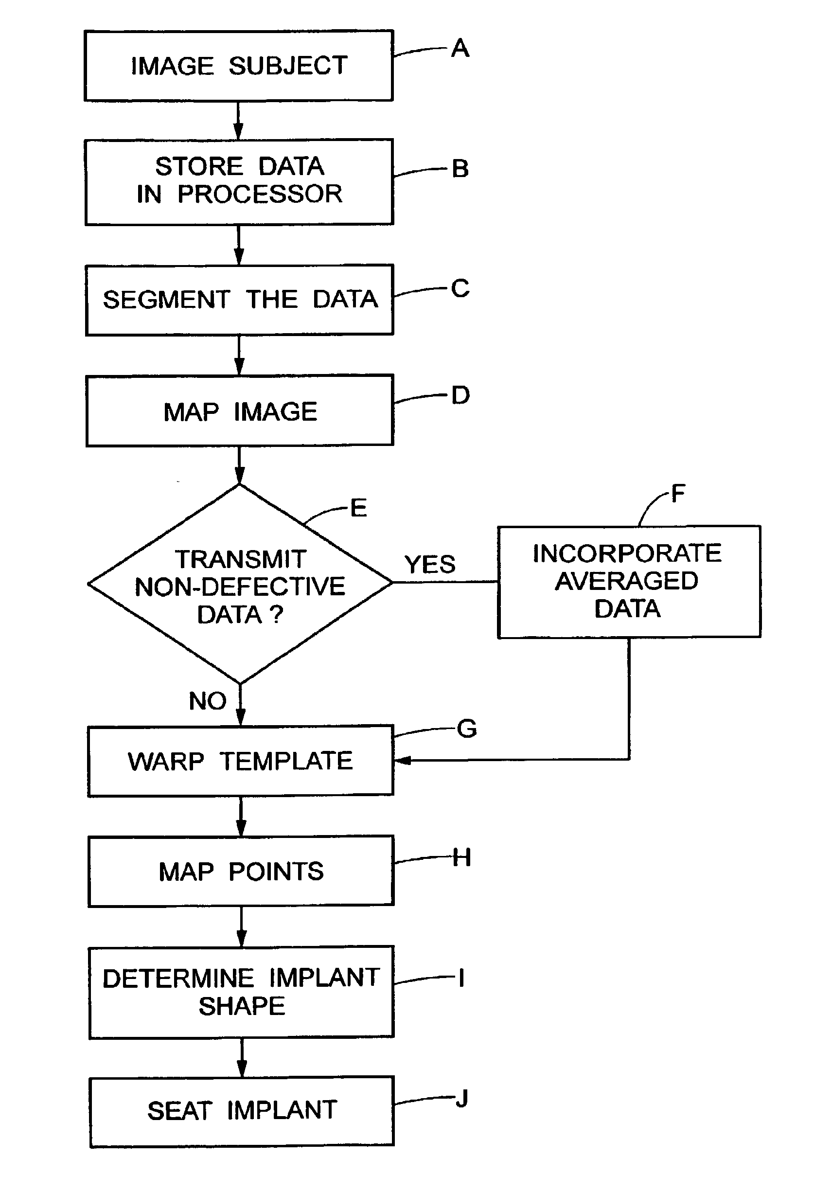
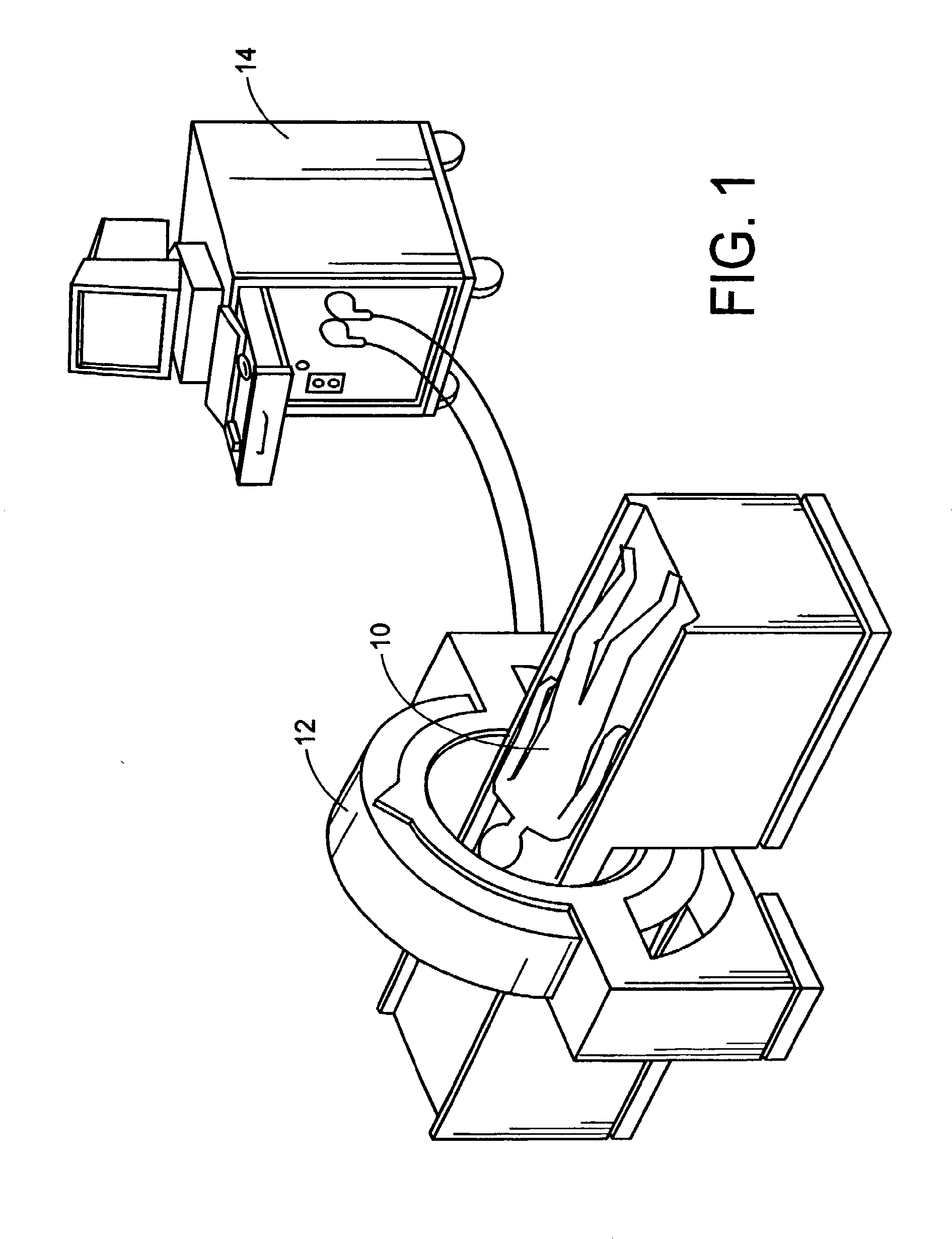
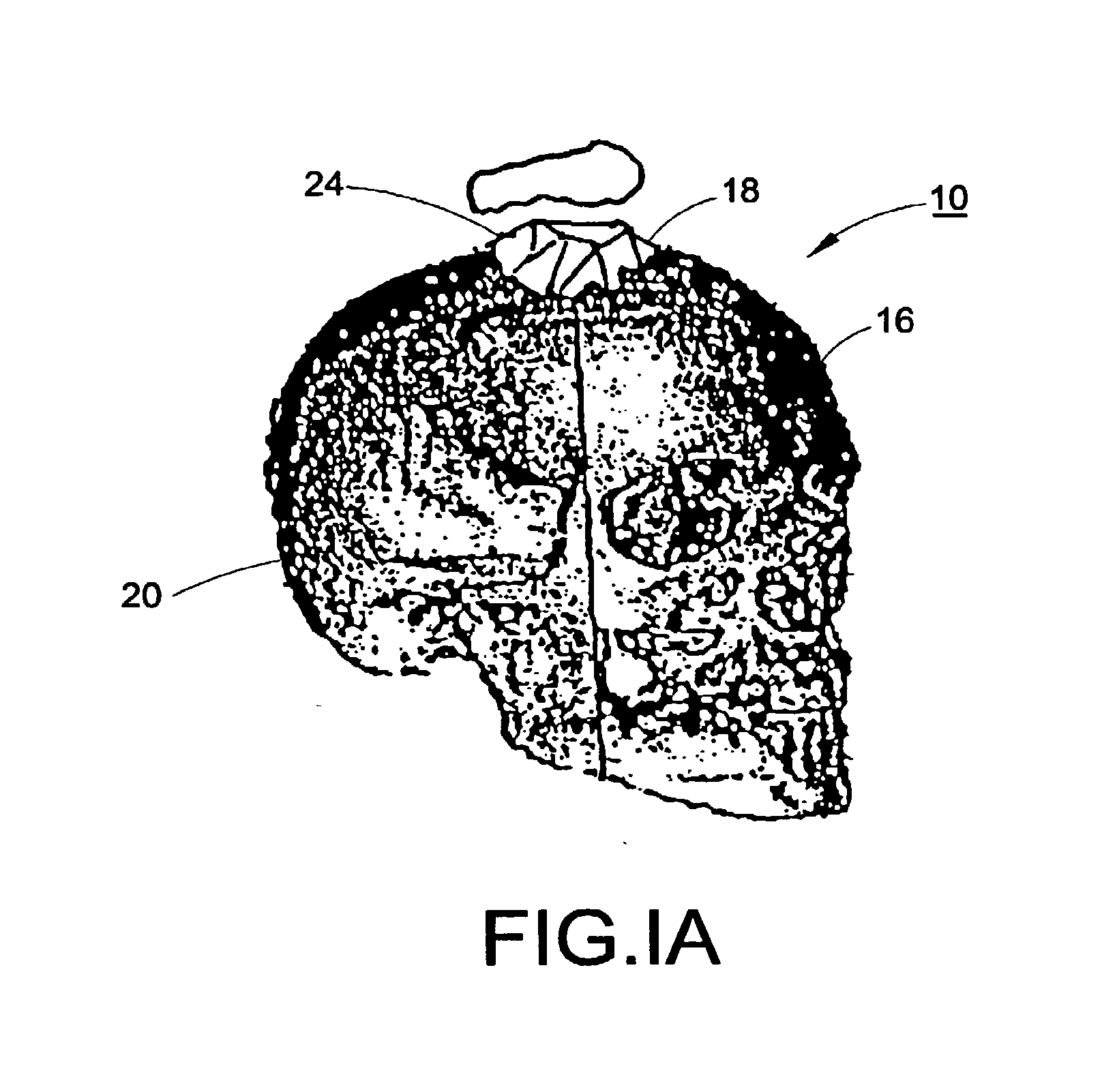
[0114]With reference to FIGS. 1, 1A, and 2, a subject 10, or patient, is imaged using an imaging device 12 in a step A. Preferably, the image is a volumetric image obtained using a computerized tomography (“CT”) scanner according to a preferred protocol. However, other images, obtained using other imaging techniques (e.g., magnetic resonance) are also contemplated. Once the data is captured from the CT scanner 12, it is stored in a processor 14 (preferably, a transportable storage medium) in a step B (although it could be transferred over a network). Then, the processor 14 segments the data in a step C for extracting a region of the image including a target tissue (e.g., liver, lung, or hard tissue such as bone) 16 of interest within the subject; the extracted region 16 includes two (2) portions (i.e., one portion having a defect 18 and one portion 20 without the defect). Preferably, the non-defective portion 20 substantially surrounds the defective portion. An external surface of t...


PUM


Abstract

A computer implemented method for determining the 3-dimensional shape of an implant to be implanted into a subject includes obtaining a computer readable image including a defective portion and a non-defective portion of tissue in the subject, superimposing on the image a shape to span the defective portion, and determining the 3-dimensional shape of the implant based on the shape that spans the defective portion.

Description

[0001]This application is a continuation of U.S. application Ser. No. 13 / 616,007, filed Sep. 14, 2012. which is a continuation of U.S. application Ser. No. 13 / 228,517, filed Sep. 9, 2011, which is a continuation of U.S. application Ser. No. 10 / 089,467, filed Mar. 27, 2002, which is a National Stage Entry of International Application PCT / US2000 / 22053, filed Aug. 11, 2000, which claims the benefit of U.S. Provisional Application Nos. 60 / 148,275, 60 / 148,277, and 60 / 148,393, which were all filed Aug. 11, 1999. All prior applications are incorporated by reference.BACKGROUND OF THE INVENTION[0002]The present invention relates to fabricating implants to replace bony structures. More specifically, the invention relates to a system and methodology for fabricating a “drop in” replacement for a particular segment of missing bony structure, in which the implant fits precisely within the contours of the missing segment and thus minimizes complications during the surgical procedure to install the...

Claims


Application Information

Patent Timeline
Patent Type & Authority Applications(United States)
IPC IPC(8): G06T7/00
CPCG06T7/0012G06T2207/10081G06T2207/20084G06T2207/30008G06T2207/30016G06T2207/30201A61F2/2875A61B5/1075A61B2576/00G06T17/00G06T2210/41A61B5/7264A61B6/03A61B5/055A61B6/501A61F2/30942A61F2002/30943G06T7/50G06T7/11Y10S128/922Y10S623/914B33Y80/00B33Y50/00G06T7/001G06T2207/10088G06T2207/30108G16H50/50G16H30/40G16H50/20G06F18/22G06T7/10G06T7/00G06T7/0002G06T7/143G06T7/174G06T7/68G06T7/564G06V2201/03G06F18/2137A61B6/032G06T15/08G06T2207/30052A61B6/505A61F2/28A61F2002/2835G06T7/0014G16H20/40G16H30/20G16H40/63
Inventor DEAN, H. DAVIDSUBRAMANYAN, KRISHNAMOORTHYMOULLAS, ALEXANDROS T.RATCHESON, ROBERT A.
Owner OSTEOPLASTICS
Why Eureka
Try Eureka