
Method and System for Injecting Low Pressure Oxygen from an Ion Transport Membrane into an Ambient or Super Ambient Pressure Oxygen-Consuming Process

a technology of ion transport membrane and oxygen-consuming process, which is applied in the direction of manufacturing tools, lighting and heating apparatus, combustion types, etc., can solve the problems of high energy consumption of separation process, large increase in cost of oxygen (for use in oxy-fuel combustion), and high cost of glass melting furna

Inactive Publication Date: 2014-01-02
AIR LIQUIDE AMERICA INC +1
View PDF8 Cites 9 Cited by
  • Summary
  • Abstract
  • Description
  • Claims
  • Application Information

AI Technical Summary

Benefits of technology

The patent describes a method and system for injecting low pressure oxygen from an ion transport membrane into an oxygen-consuming process. The system includes a reactor, a first ion transport membrane, a source of high velocity gas, and an oxygen injection device. The high velocity gas is injected into the oxygen-consuming process through an inner tube and an outer tube, creating a vacuum that sucks the oxygen from the membrane. The method and system can be used in various industrial processes such as combustion, aluminum production, and cement kiln. The technical effect of the patent is to provide a more efficient and effective method for injecting low pressure oxygen into various industrial processes.

Problems solved by technology

However, economically speaking, oxygen (for use in oxy-fuel combustion) is costly for glass melting furnaces.
The main cost increase is the separation of oxygen from air using a cryogenic air separation unit (ASU).
This separation process requires a great deal of energy.
However, handling pure O2 at a temperature higher than 650° C. is very difficult and there are very few materials that have been shown to reliably withstand such high temperatures in the O2 rich environment.
The O2 product may be available at a desirably high pressure of about 2.2 bar, but at the expense of relatively low recoveries.
There are difficulties experienced when attempting to inject such low pressure O2 into the furnace.
Compressing O2 at 900° C. is considered undesirable due to the significant material constraints noted above.
Cooling the O2 down then compressing it is another option, but such an approach will decrease the energy efficiency.

Method used


Image

  • Method and System for Injecting Low Pressure Oxygen from an Ion Transport Membrane into an Ambient or Super Ambient Pressure Oxygen-Consuming Process
  • Method and System for Injecting Low Pressure Oxygen from an Ion Transport Membrane into an Ambient or Super Ambient Pressure Oxygen-Consuming Process
  • Method and System for Injecting Low Pressure Oxygen from an Ion Transport Membrane into an Ambient or Super Ambient Pressure Oxygen-Consuming Process

Examples


Embodiment Construction

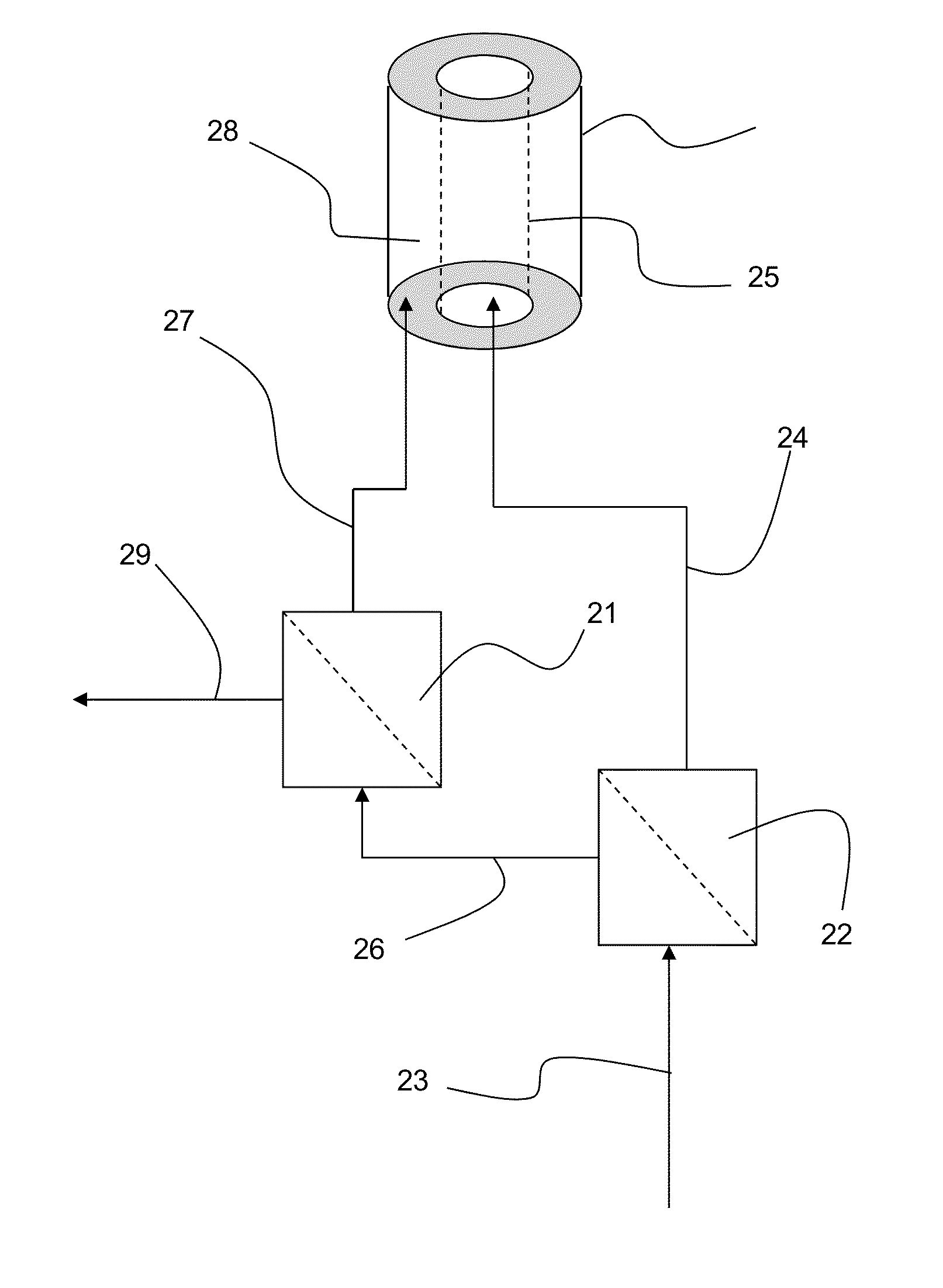
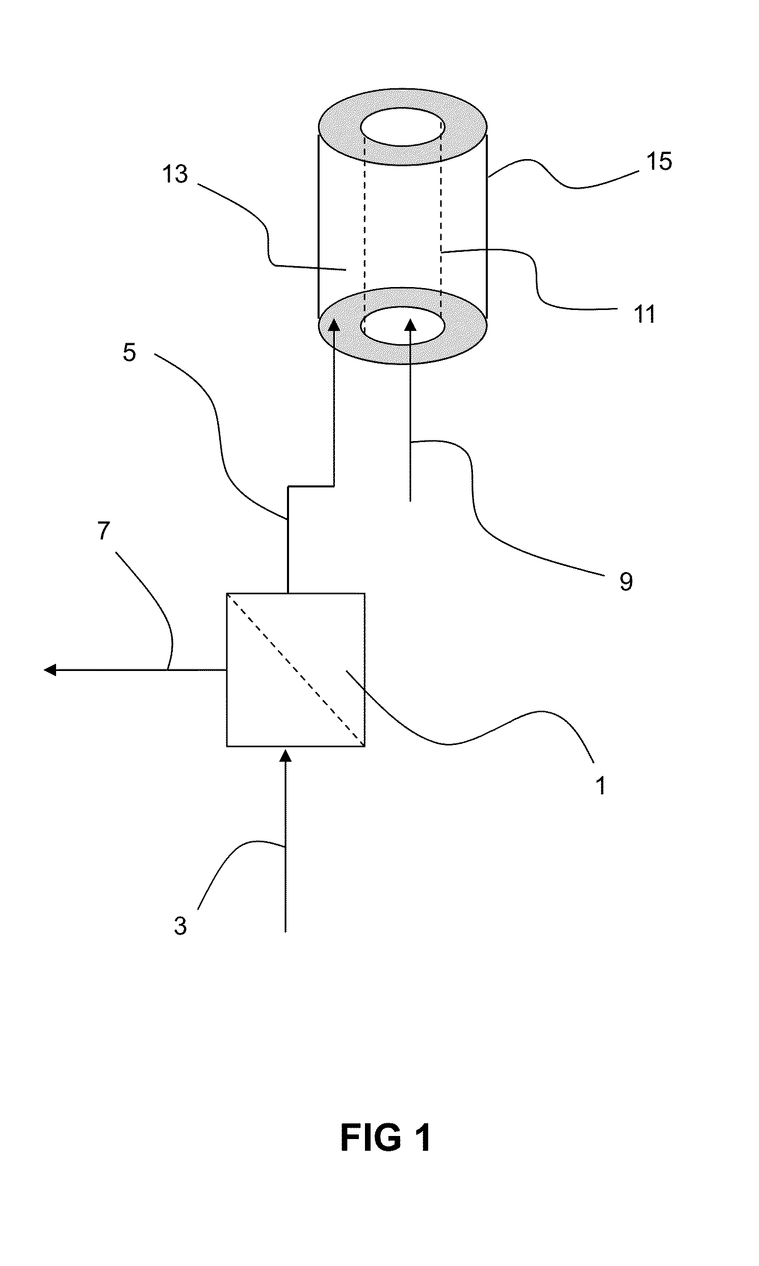
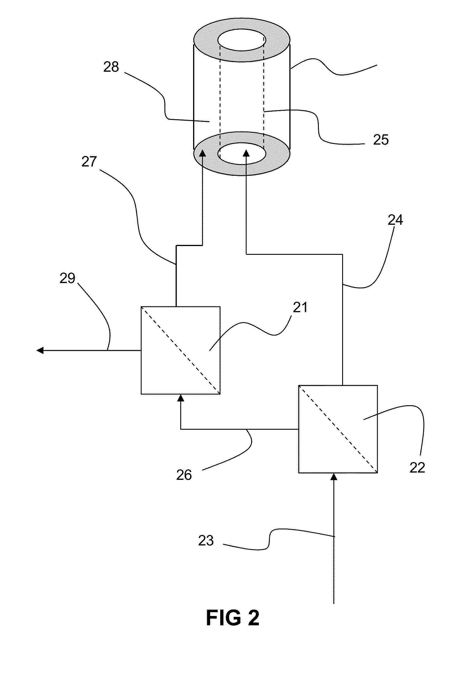
[0052]In this invention, sub ambient pressure oxygen that is permeated from an ion transport membrane is injected into an oxygen-consuming process from an oxygen injection device. The oxygen injection device comprises an outer tube concentrically disposed around an inner tube. The outlet of the inner tube and an outlet of an annular space in between the inner and outer tubes feed into an interior of a reactor in which the oxygen-consuming process takes place. A high velocity gas is injected into the reactor from the inner tube. Expansion of the high velocity gas at the outlet of the inner tube causes oxygen to be sucked from the annular space and, hence, sucked from the ion transport membrane.

[0053]The reactor containing the oxygen-consuming process is not limited. Typical types of reactors include oxy-combustion furnaces, oxy-combustion boilers, aluminum furnaces, cement kilns, electric arc furnaces having oxygen lances or oxy-combustion burners, industrial melting furnaces, and bl...


PUM

PropertyMeasurementUnit
velocityaaaaaaaaaa
pressureaaaaaaaaaa
temperatureaaaaaaaaaa

Abstract

A stream of sub ambient oxygen from an ion transport membrane is injected into an ambient pressure or super ambient pressure oxygen-consuming process through an annular space in between concentrically disposed inner and outer tubes where a high velocity gas is injected into the process from the inner tube.

Description

CROSS-REFERENCE TO RELATED APPLICATIONS[0001]None.BACKGROUND[0002]1. Field of the Invention[0003]The present invention relates to injection of oxygen from ion transport membranes.[0004]2. Related ArtOxy-Combustion in Glass Manufacturing Process[0005]Air-fired glass melting furnaces has been converted to oxygen-fired technology (i.e., oxy-combustion with oxygen concentrations in the oxidant of up to 100%) primarily due to environmental regulations. Oxy-combustion is one of the most thermally efficient and cost-effective ways to enable glass manufacturers to meet NOx emissions restrictions. Compared with air-fired combustion, oxy-combustion has the potential to reduce NOx emissions by up to 85%.[0006]Besides the reduction of NOx emissions, the oxy-combustion has several other significant advantages over traditional air-fired combustion processes:[0007]the mass and volume of the flue gas are reduced by ˜75%;[0008]there is less heat loss in the flue gas due to the reduction of the flue ...

Claims


Application Information

Patent Timeline
Patent Type & Authority Applications(United States)
IPC IPC(8): F23L7/00F23L15/00
CPCF23L7/007F23L15/00C01B13/0251C01B2203/025C03B5/2353Y02E20/34Y02P40/50
Inventor HUANG, WEIWANG, JUSTIN JIANTSIAVA, REMI PIERRE
Owner AIR LIQUIDE AMERICA INC
Learn More