Eureka AIR delivers breakthrough ideas for toughest innovation challenges, trusted by R&D personnel around the world.

Method and apparatus for sweetening and/or dehydrating a hydrocarbon gas, in particular a natural gas

Active Publication Date: 2014-01-02
SIME
View PDF7 Cites 17 Cited by
  • Summary
  • Abstract
  • Description
  • Claims
  • Application Information

AI Technical Summary

Benefits of technology

The present invention provides a method and apparatus for sweetening and / or dehydration of a variable flowrate hydrocarbon gas stream that can maintain separation efficiency at a determined level even if the flow rate reduces progressively. This invention is particularly useful for treating natural gas from wells, as it can maintain efficient sweetening and dehydration throughout the whole useful life of the well. Additionally, this invention is tolerant of significant flow rate changes, which allows for smaller treatment units compared to prior art solutions.

Problems solved by technology

Furthermore, the acid compounds make the gas unsuitable for a large number of uses.
Nevertheless, the moisture may cause ice and hydrocarbon hydrates to form, when the gas is expanded after extraction.
The ice can block passageways, and damage the equipment and the piping.
The water that is present in the gas may also form corrosive pools within the gas pipelines.
The same problems also occur with other fuel-gas mixtures, for example light gas fractions from crude oil atmospheric distillation.
Such towers cannot effectively treat a very low flowrate, such as the flowrate that may generally be extracted after even a few years of life of the well.
This is a particularly relevant problem if packed towers are used.
In fact, the movement of the platforms caused by the waves does not allow to operate plate towers, or makes it disadvantageous, because plate towers do not allow a steady liquid hold-up to be maintained on the trays.
Accordingly, this way to reduce the height of the tower unavoidably increases its overall lateral dimensions, which is a disadvantage in an installation on structures that have a limited space availability.
Such an apparatus is not well-suited for sweetening / dehydration operations of a large number of gases that require such treatment.
In an embodiment, a sweetening / regeneration process is carried out in side-by-side chambers, which may lead to important problems due to unwanted heat exchange and to unfavourable temperature profiles, since the sweetening temperature of processes is normally quite lower than the temperature at which the corresponding absorption liquid is regenerated, as in the case of amines.
Furthermore, the gas and liquid passageway according to the above-mentioned document, as shown in the drawings, should be made with ducts arranged within the shell, which can disturb the gas and liquid flow and cause a loss of efficiency of the apparatus.
However, the operating pressure and temperature differences at which the portions operate are limited.

Method used


Image

  • Method and apparatus for sweetening and/or dehydrating a hydrocarbon gas, in particular a natural gas
  • Method and apparatus for sweetening and/or dehydrating a hydrocarbon gas, in particular a natural gas
  • Method and apparatus for sweetening and/or dehydrating a hydrocarbon gas, in particular a natural gas

Examples


Embodiment Construction

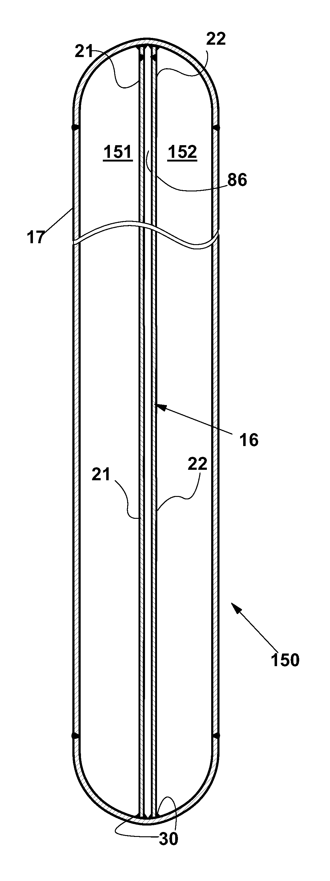
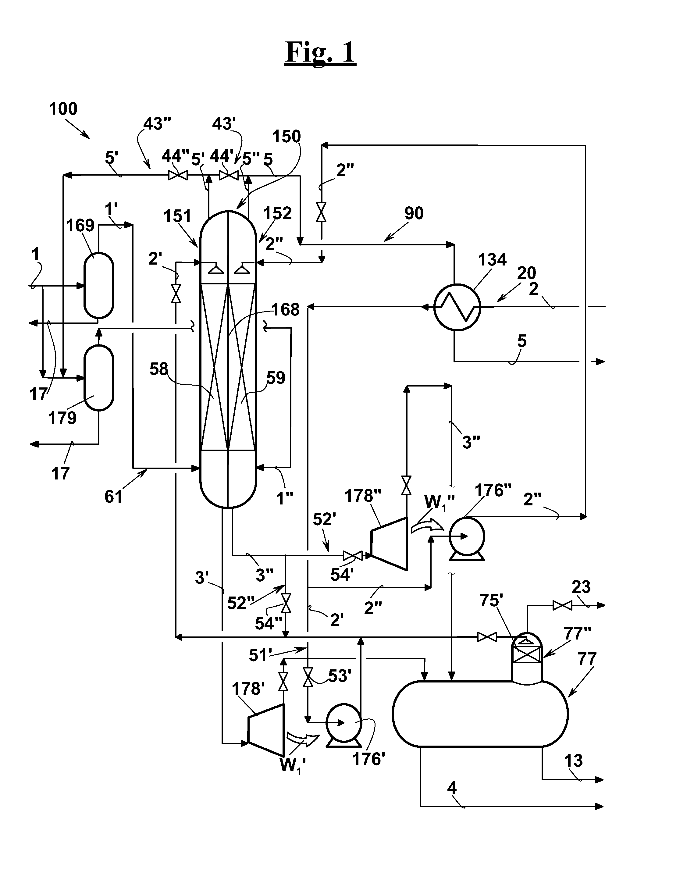
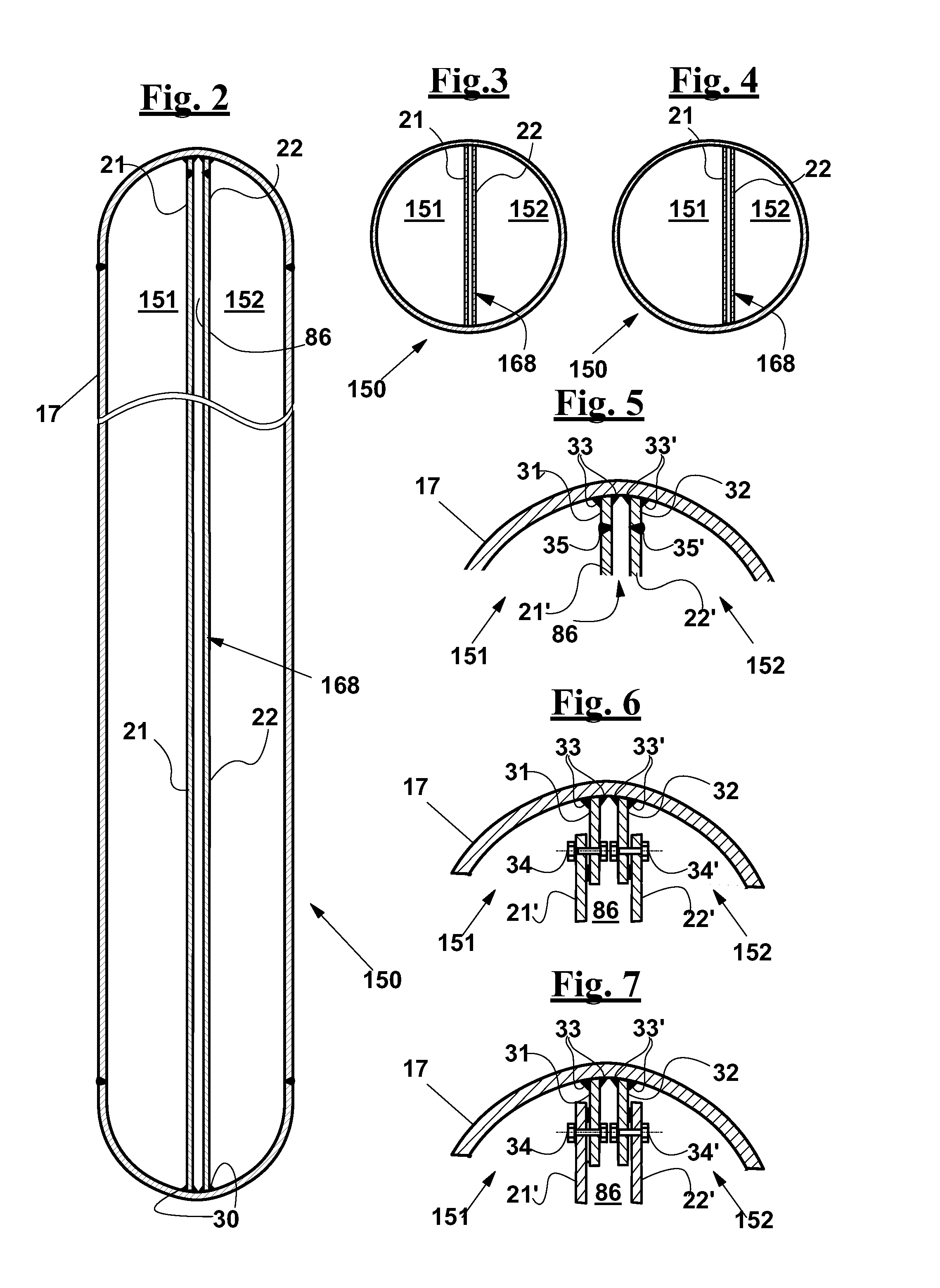
[0142]With reference to FIG. 1, a method and an apparatus 100 are described for a treatment of removing a component from a hydrocarbon gas stream, in particular a sweetening treatment of an acid natural gas. A vertical sweetening tower 150 comprises an inner partition wall 168 that extends longitudinally within tower 150. Inner partition wall 168 defines a first sweetening chamber 151 and a second sweetening chamber 152 within tower 150, which are separated by inner partition wall 168.

[0143]At least one part 1′ of acid gas 1, as this is extracted from a well or from a gasfield, is subjected to a gravitational solid dust and liquid matter removal in a cyclone separator 169, or in an equivalent equipment. Acid gas 1 is then fed into first sweetening chamber 151 through a second inlet port 172. Acid gas 1 turns into an at least partially sweetened gas 5′ in first sweetening chamber 151, from which it is extracted through a second outlet port 174. First sweetening chamber 151 is also su...


PUM

PropertyMeasurementUnit
Fractionaaaaaaaaaa
Fractionaaaaaaaaaa
Lengthaaaaaaaaaa

Abstract

A method for removing acidity and / or moisture from a hydrocarbon gas, in particular from a natural gas or a refinery gas fraction or a syngas, by absorption into a sweetening liquid and into a dehydration liquid, that are adapted to extract acid compounds or water from the gas, respectively. The method provides a step of prearranging a vertical elongated container (150) comprising at least one inner partition wall (168) that defines at least two treatment chambers within said container (151,152), a step of feeding a treatment liquid from the above into at least one of the two chambers (251,252) and feeding the gas to be treated from below into at least one same treatment chamber. It is also provided a step of selecting a treatment mode, wherein the gas flows along the two treatment chambers in a parallel or in a series arrangement, or one chamber being excluded; in particular the series-mode or the exclusion mode is actuated when the flowrate of the gas decreases below a minimum threshold value, while the parallel-mode is actuated when the flowrate of the gas rises above a maximum threshold value. An apparatus comprising at least such a container and a gas convey selective convey means (44′,44″), for actuating said treatment modes, in particular responsive to a flowrate of the gas. The apparatus and the method according to the invention allow to maintain the sweetening and / or dehydration efficiency, in particular in the case of a progressive reduction of the flowrate of natural gas that can be obtained from a well or gasfield.

Description

SCOPE OF THE INVENTION[0001]The present invention relates to a method and to an apparatus for removing acid compounds, in particular for removing sulphur compounds (sweetening) and / or moisture (dehydration) from a hydrocarbon gas, by absorption into respective absorption liquids.[0002]In particular, the method and the apparatus are adapted to treat a natural gas as this is extracted from a gas extraction unit that comprises at least one well.BACKGROUND OF THE INVENTION[0003]The raw natural gas, as extracted from wells, often contains acid compounds, in particular carbon dioxide and hydrogen sulfide. The natural gas may also contain moisture. The acid compounds, in combination with the moisture make the gas aggressive to the materials of the equipment in which the gas has to be stored and / or transformed. Furthermore, the acid compounds make the gas unsuitable for a large number of uses.[0004]Nevertheless, the moisture may cause ice and hydrocarbon hydrates to form, when the gas is ex...

Claims


Application Information

Patent Timeline
IPC IPC(8): C10L3/10B01D53/18
CPCC10L3/103B01D53/18C10L3/104C10L3/106B01D3/141B01D53/1462B01D53/263B01D2251/304B01D2251/604B01D2252/2026B01D2252/20484B01D2252/20489B01D2257/304B01D2257/504B01D2257/80B01D2258/02B01D2258/05C10L3/101C10L3/102Y02P70/10B01D2252/2023C10L2290/541
Inventor FAVILLI, STEFANOSCIBOLA, LUCIANO
Owner SIME
Why Eureka
Eureka Blog
Learn More