Mass damper

a mass damper and damper technology, applied in the direction of dampers, shock absorbers, mechanical devices, etc., can solve the problems of not always possible or practical, vibration is a common problem, and the tuning frequency is not changed during the use of the damper, so as to reduce the tension in the spring elements, the effect of small mass damper and simple structure of the movable spring support elements

Active Publication Date: 2014-01-09
WARTSILA FINLAND OY
View PDF4 Cites 47 Cited by
  • Summary
  • Abstract
  • Description
  • Claims
  • Application Information

AI Technical Summary

Benefits of technology

[0012]According to an embodiment of the invention, the parts of the frame parallel to the vibration direction of the mass damper are resilient for allowing displacement of the fixing points of the spring elements. When the mass elements move, a force pointing inwards is directed at the fixing points of the spring elements. If the frame of the mass damper is made resilient, the tension in the spring elements can be reduced.
[0013]According to an embodiment of the invention, the mass elements are provided with recesses for accommodating the movable spring support elements. This embodiment enables small size of the mass damper and simple structure of the movable spring support elements.
[0014]According to an embodiment of the invention, the mass elements are connected to each other with at least one stud bolt. According

Problems solved by technology

Vibrations are a common problem in many machines comprising reciprocating or rotating parts.
However, this is not always possible or practical for instance because of cost-efficiency reasons.
A

Method used


Image

  • Mass damper
  • Mass damper
  • Mass damper

Examples


Embodiment Construction

[0022]Embodiments of the invention are now described in more detail with reference to the accompanying drawings.

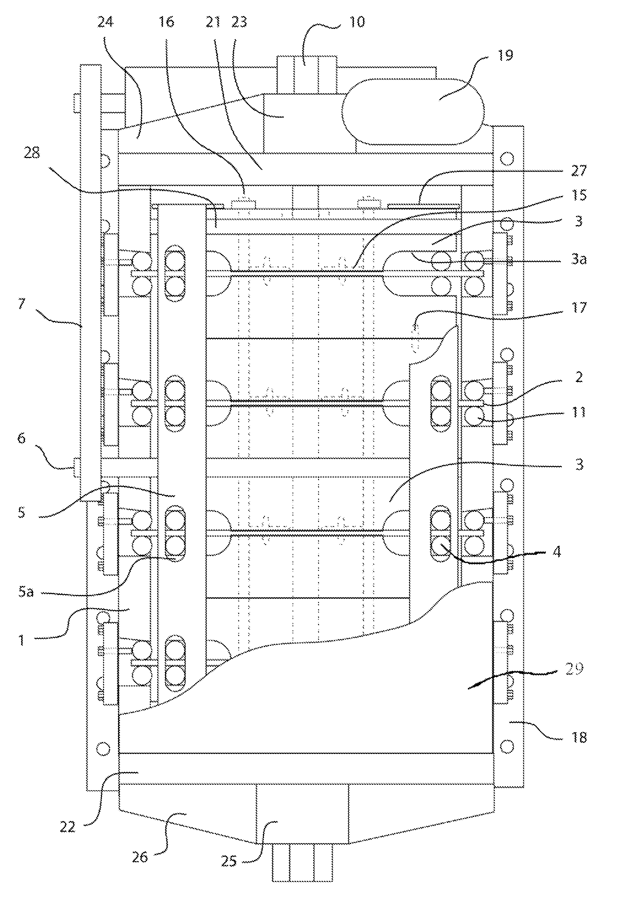
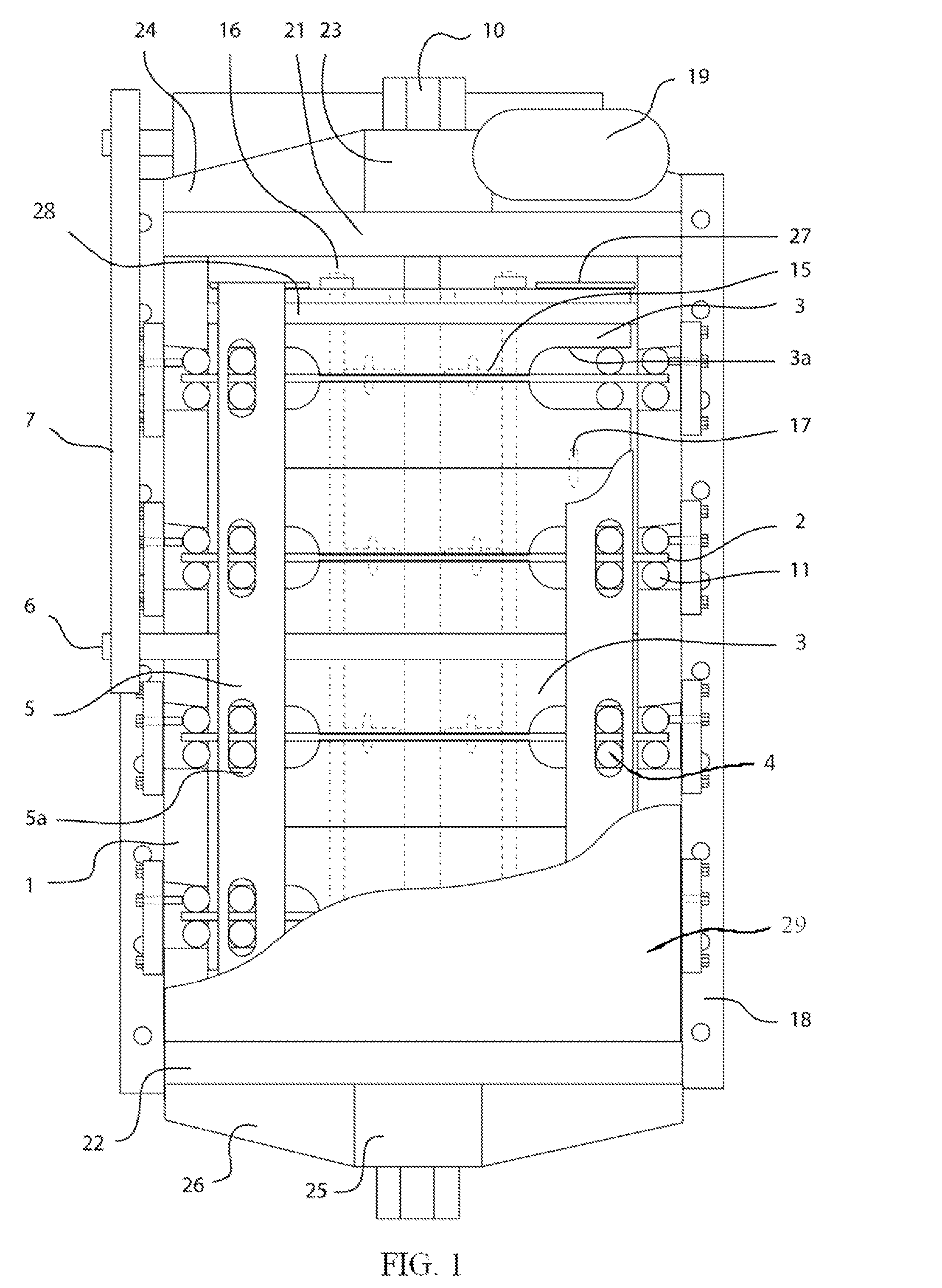
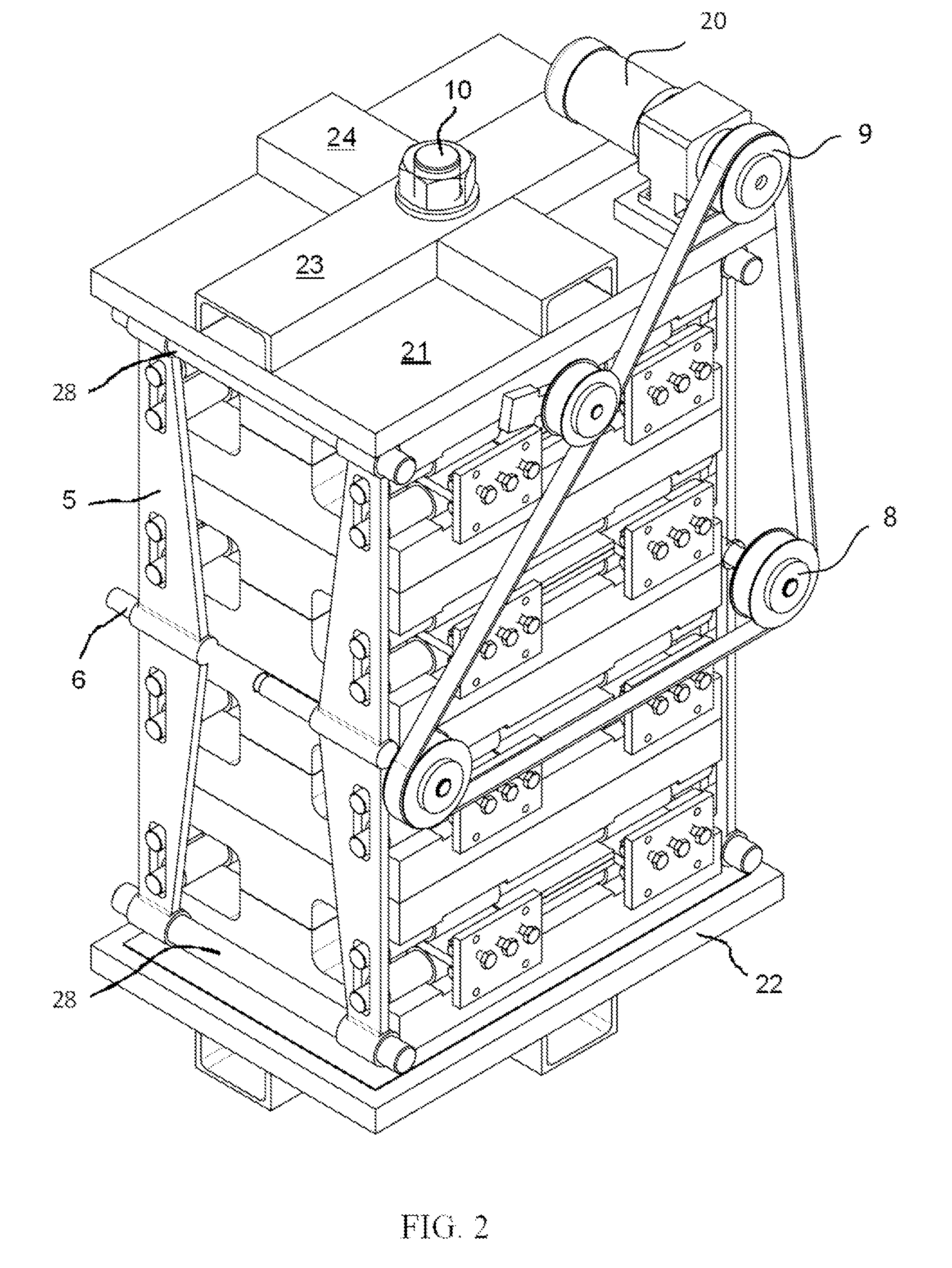
[0023]An adaptive tuned mass damper according to the present invention comprises a frame 1, at least one spring element 2, at least one mass element 3, and at least one movable spring support element 4. The spring element 2 is connected from its ends to the frame 1. The mass damper is intended for reducing vibrations of for instance an internal combustion engine, a turbocharger of an internal combustion engine, or some other vibrating device. In the embodiment of FIGS. 1-5, the mass damper comprises a plurality of spring elements 2, movable spring support elements 4 and mass elements 3. The spring elements 2 are leaf springs that are arranged inside the frame 1 so that both ends of the spring elements 2 are fixed to the frame 1. The term ‘leaf spring’ refers here to springs that can consist either of a single elongated resilient element or a plurality of elements arranged ...


PUM


Abstract

A tuned mass damper comprising a frame, at least one bendable spring element being connected from its ends to the frame, and at least one mass element being connected to the spring element at a distance from the ends of the spring element, at least one movable spring support element for adjusting the tuning frequency of the damper, and means for moving the spring support element.

Description

TECHNICAL FIELD OF THE INVENTION[0001]The present invention relates to an adaptive tuned mass damper according to the preamble of claim 1.BACKGROUND OF THE INVENTION[0002]Vibrations are a common problem in many machines comprising reciprocating or rotating parts. Vibrations occur for instance in internal combustion engines or in the auxiliaries of them, such as in turbochargers. Vibrations can be reduced by modifying the components, for instance by increasing the stiffness of some parts of the structure.[0003]However, this is not always possible or practical for instance because of cost-efficiency reasons. Therefore, different vibration dampers have been developed for reducing vibrations of machines or machine parts. A vibration damper can be implemented as a tuned mass damper, an adaptive tuned mass damper, a semi active damper, or an active damper. A typical mass damper comprises a spring-supported movable mass that can move in a space that is filled with a damping medium, such as...

Claims


Application Information

Patent Timeline
IPC IPC(8): F16F7/104
CPCF16F7/104F16F2238/022F16F15/073F16F15/02F16F7/10F16F15/12F16F7/1011
Inventor MIKONAHO, HEIKKITIENHAARA, HANNUANDERSSON, PETERKLINGE, PAULKOKKONEN, PETTERISAINIO, HANNU
Owner WARTSILA FINLAND OY
Why Eureka
Try Eureka