Light-emitting diode fixture with an improved thermal control system

a technology of thermal control system and light-emitting diodes, which is applied in lighting and heating apparatus, cathode-ray/electron beam circuit elements, lighting heating/cooling arrangements, etc., can solve the problems of thermal stress of light-emitting diodes, increase in the temperature of light-emitting diodes, and additional heating of pn junctions

Active Publication Date: 2014-01-09
MP DESIGN
View PDF3 Cites 16 Cited by
  • Summary
  • Abstract
  • Description
  • Claims
  • Application Information

AI Technical Summary

Problems solved by technology

A significant portion of the electrical energy is converted to thermal energy which results in an increase in the temperature of the light-emitting diode.
The increased current causes additional heating of the PN junction and may thermally stress the light-emitting diode.
Thermally stressed light-emitting diodes lose efficiency and their output is diminished.
Thermally stressed light-emitting diodes may also impose an increased load on related driver components causing their temperature to increase as well.
This may result in broken wire bonds, delaminating, internal solder joint detachment, damage to die-bond epoxy, and lens yellowing.
If nothing is done to control the increasing temperature of the light emitting diode, the PN junction may fail, possibly resulting in thermal runaway and catastrophic failure.
However, the need for a controller, typically in the form of a microprocessor, increases the number of components in the thermal control system and thereby increases manufacturing costs.

Method used


Image

  • Light-emitting diode fixture with an improved thermal control system
  • Light-emitting diode fixture with an improved thermal control system
  • Light-emitting diode fixture with an improved thermal control system

Examples


Embodiment Construction

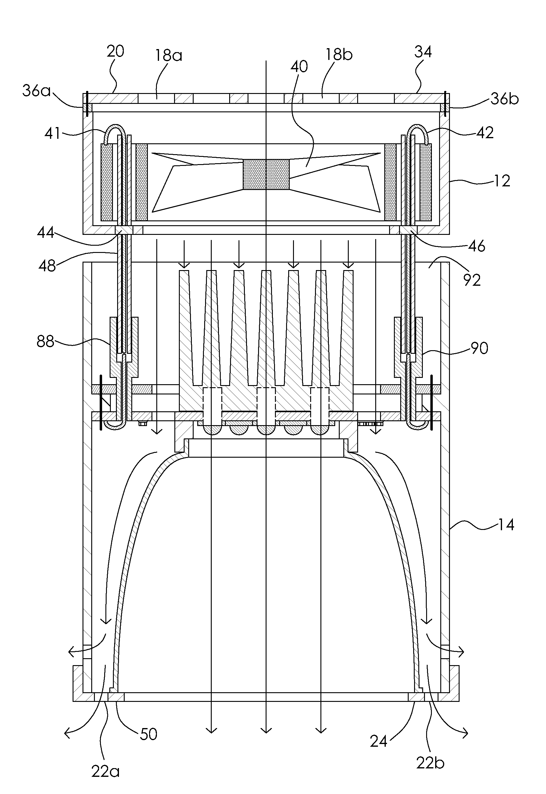
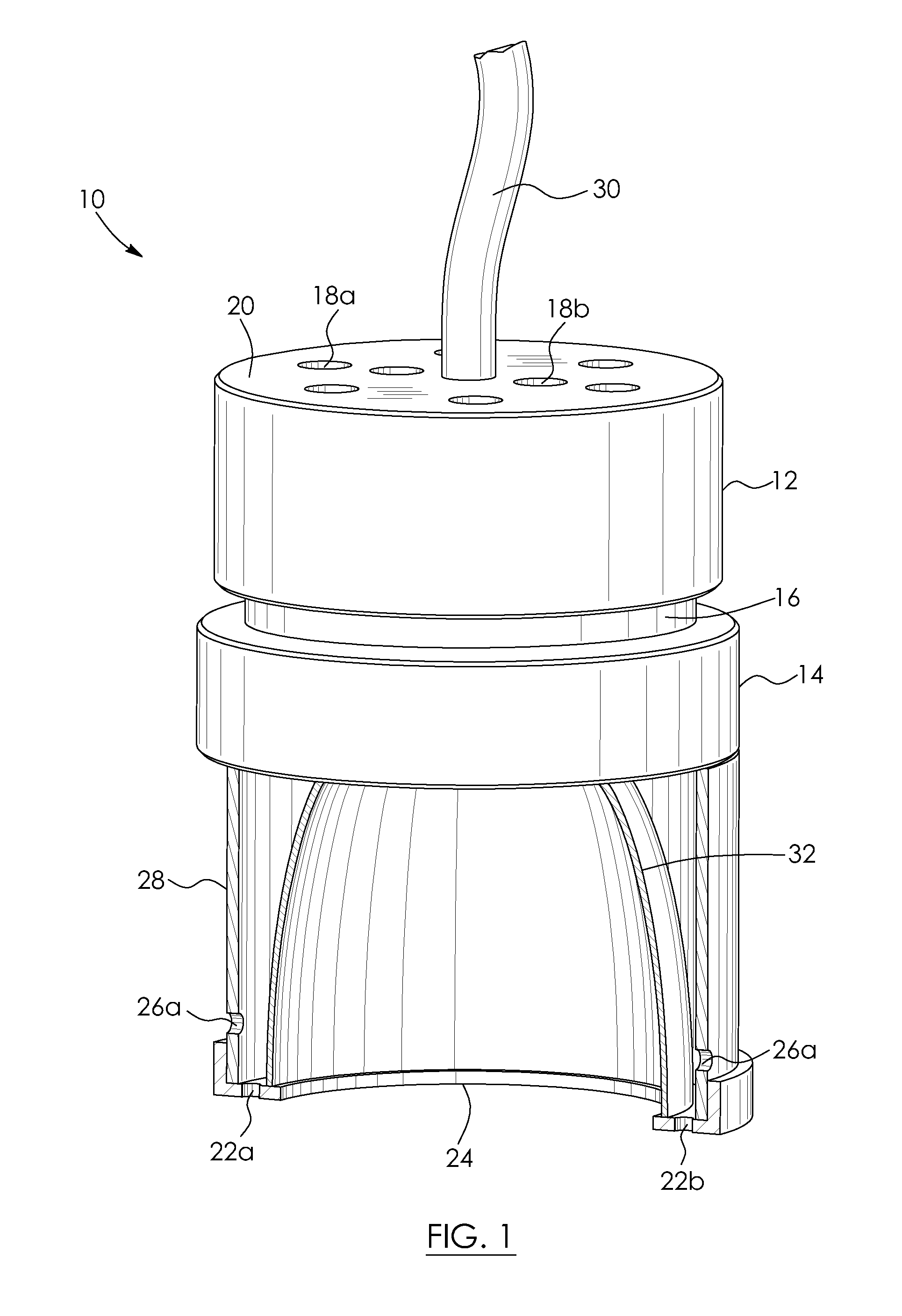
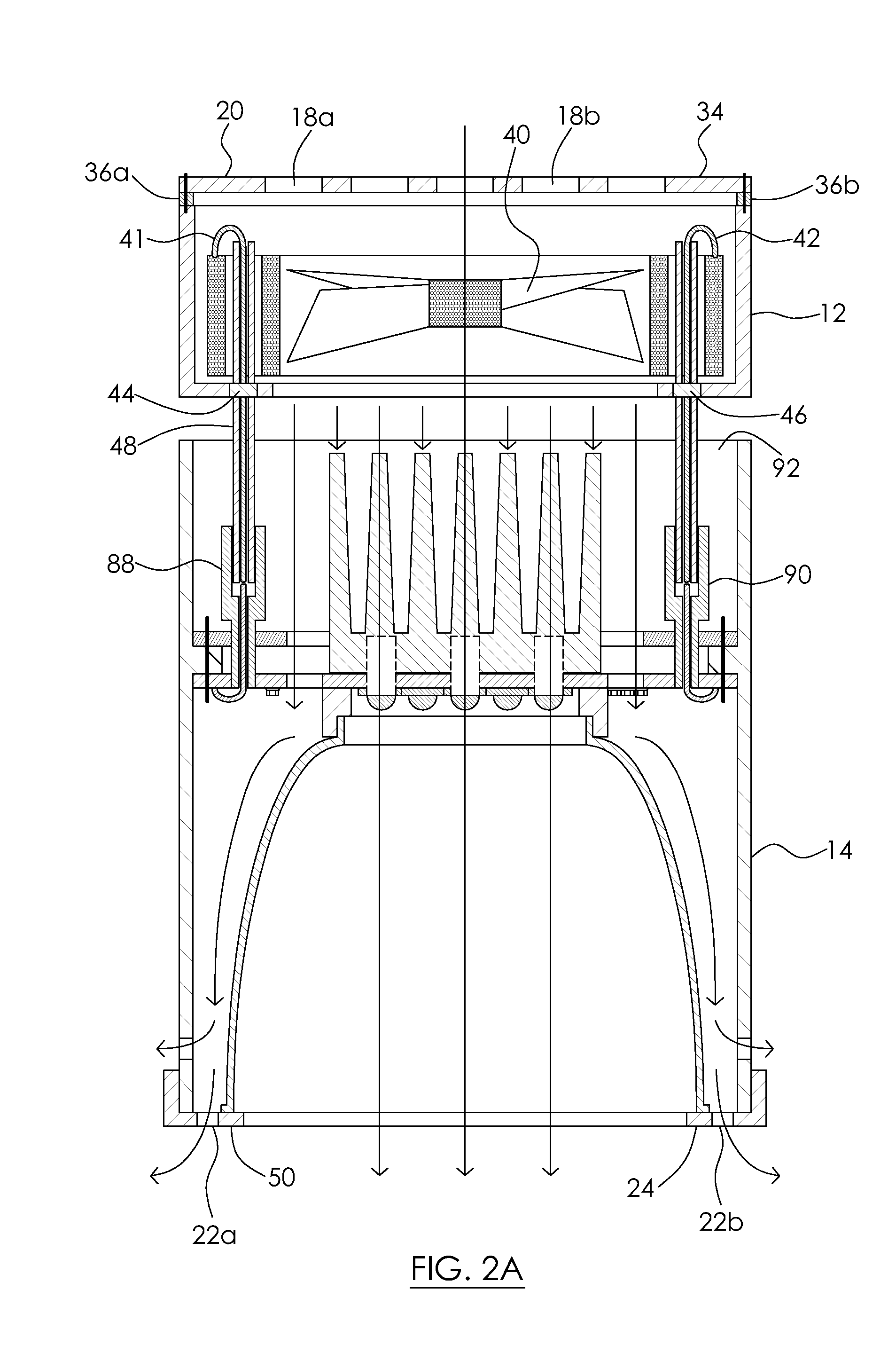
[0017]Referring to the drawings and first to FIG. 1 an improved light-emitting diode fixture 10 is shown. The light-emitting diode fixture 10 includes a first housing portion 12 and a second housing portion 14. The first housing portion 12 and second housing portion 14 are spaced apart and coupled by a connector 16. The connector is hollow and permits fluid communication between the first housing portion 12 and the second housing portion 14. In this example the connector 16 is integral with the first housing portion 12. In other examples the connector may be integral with the second housing portion or the connector may be a separate component. The first housing portion 12 is vented and has a plurality of openings, for example openings 18a and 18b, which extend through an end 20 of the first housing portion which is opposite of connector 16. The second housing portion 14 is also vented and has a plurality of openings, for example openings 22a and 22b, which extend through an end 24 o...


PUM


Abstract

A light-emitting diode fixture comprises spaced-apart first and second housing portions. There is a cooling device disposed within the first housing portion. The cooling device is in fluid communication with the second housing portion. First and second printed circuit boards are disposed within the second housing portion. A light-emitting diode and a negative coefficient thermistor array are mounted on the first printed circuit board. The light-emitting diode and the negative coefficient thermistor array are each thermally coupled to a heat sink. A rectifier is mounted on the second printed circuit board. The rectifier is electrically connected in series with the negative coefficient thermistor array and the cooling device. Current used to power the cooling device flows from the rectifier through the negative coefficient thermistor array to the cooling device.

Description

BACKGROUND OF THE INVENTION[0001]1. Field of the Invention[0002]The present invention relates to a light-emitting diode fixture and, in particular, to a light-emitting diode fixture with an improved thermal control system.[0003]2. Description of the Related Art[0004]Light-emitting diodes, like any semiconductor, emit heat during their operation. This is because not all of the electrical energy provided to a light-emitting diode is converted to luminous energy. A significant portion of the electrical energy is converted to thermal energy which results in an increase in the temperature of the light-emitting diode. In resistor driven circuits, as the temperature of the light-emitting diode increases, the forward voltage drops and the current passing through the PN junction of the light-emitting diode increases. The increased current causes additional heating of the PN junction and may thermally stress the light-emitting diode.[0005]Thermally stressed light-emitting diodes lose efficien...

Claims


Application Information

Patent Timeline
Patent Type & Authority Applications(United States)
IPC IPC(8): H01J7/26H01J7/44H05B44/00
CPCF21V29/763F21V29/505F21V29/507F21V29/71F21V29/83F21Y2105/10F21Y2115/10H05B45/00
Inventor KORNITZ, ALEXANDERPOSPISIL, MIREK
Owner MP DESIGN
Why Eureka
Try Eureka