Light emitting device, lighting system, headlight, and vehicle
- Summary
- Abstract
- Description
- Claims
- Application Information
AI Technical Summary
Benefits of technology
Problems solved by technology
Method used
Image

Examples
example 1
[0155]FIG. 4 is a block diagram which illustrates a circuit configuration of the laser driving unit 102 (step-up type) in Example 1. It is an example of a step up circuit which is used when a voltage necessary for driving of the laser light source 1 is higher than a voltage of the power source E. In addition, the laser driving unit 102 in the Example 1 is used when a laser light source 1 includes a plurality of LD chips 11, and slightly more LD chips (number of 3 and 4 in series or more) are connected in series.
[0156]As illustrated in FIG. 4, the laser driving unit includes a main switching element 105, a coil 1021, a diode 1022, a current detecting resistor 1024, a differential amplifier 1025, a switching control unit 1026, and the above described output switching element 103. In addition, an end of the coil 1021 is connected to the power source E. In addition, a separate switching element may be provided between the power source E and the coil 1021.
[0157]In addition, the laser dri...
example 2
[0166]Subsequently, FIG. 5 is a block diagram which illustrates a circuit configuration of a laser driving unit 102 in Example 2 (step-up type).
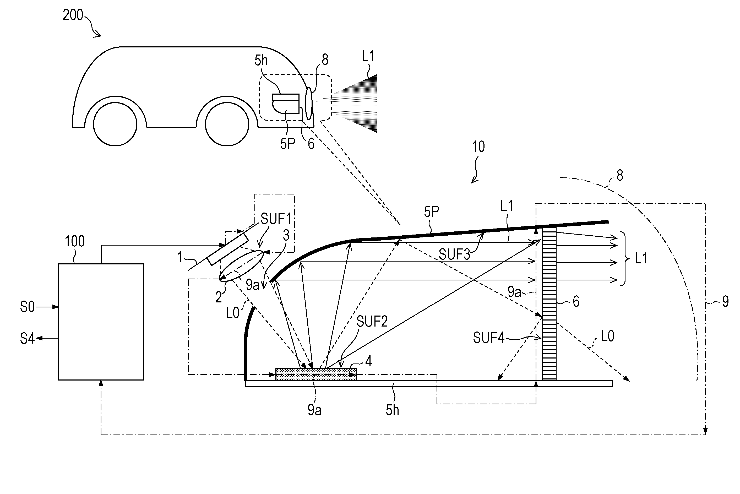
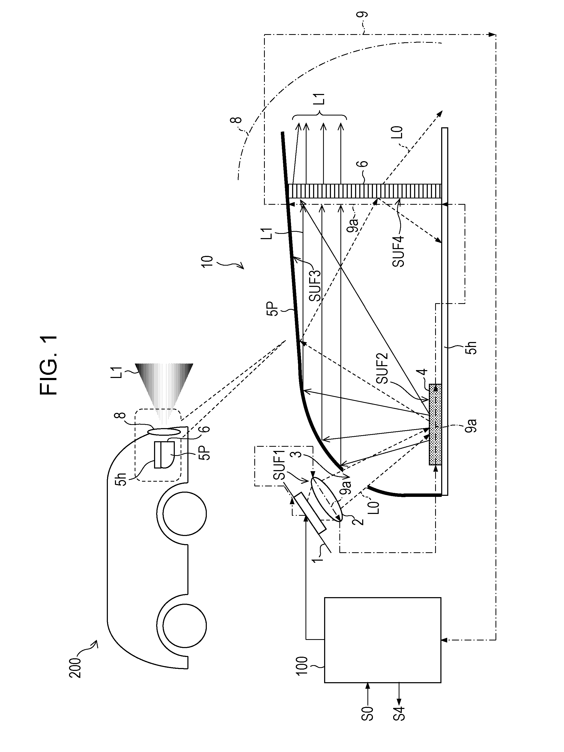
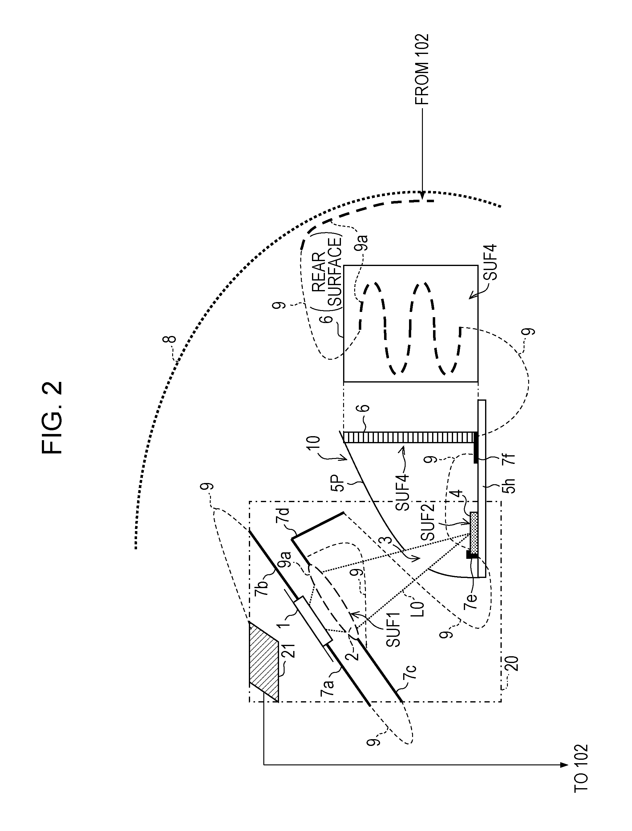
[0167]A difference in the laser driving unit 102 in Example 2 from that in Example 1 is that a part of wiring 9 (security wire) which is guided to a laser light source 1, a lens for excitation 2, a luminous body 4, a half parabolic mirror 5P, a metal base 5h, a laser cut filter 6, fixing members 7a to 7f, the surface, or the vicinity of a sealing housing 20, and a seal 21 is a portion which is denoted by a dashed line (wiring on reference potential side).
[0168]Accordingly, even if a part of the wiring 9 comes into a fault contact with another electric-equipment system, it is possible to prevent a damage of the laser light source 1, since an excessive current or voltage in the forward direction or reverse direction is not applied to the laser light source 1.
[0169]In addition, when routing of the wiring 9 is long, there is a case in which a ne...
example 3
[0172]FIG. 6 is a block diagram which illustrates a circuit configuration of a laser driving unit 102 (step-down type) in Example 3. It is an example of a step-down circuit which is used in a case in which a voltage which is necessary for driving a laser light source 1 is lower than a voltage of a power source E. In addition, the laser driving unit 102 in Example 3 is used when the number of series of LD chips 11 included in the laser light source 1 is small.
[0173]As illustrated in FIG. 3, the laser driving unit 102 includes a main switching element 105, a coil 1021, a diode 1022, a current detecting resistor 1024, a differential amplifier 1025, a switching control unit 1026, and the above described output switching element 103. In addition, one end of the coil 1021 is connected to a power source E. In addition, a separate switching element may be provided between the power source E and the coil 1021.
[0174]In addition, the laser driving unit 102 in Example 3 is connected to the lase...
PUM
 Abstract
Description
Claims
Application Information
 - Generate Ideas
- Intellectual Property
- Life Sciences
- Materials
- Tech Scout
- Unparalleled Data Quality
- Higher Quality Content
- 60% Fewer Hallucinations
Browse by: Latest US Patents, China's latest patents, Technical Efficacy Thesaurus, Application Domain, Technology Topic, Popular Technical Reports.
© 2025 PatSnap. All rights reserved.Legal|Privacy policy|Modern Slavery Act Transparency Statement|Sitemap|About US| Contact US: help@patsnap.com