Inserting virtual carrier in conventional OFDM host carrier in communications system

a virtual carrier and communication system technology, applied in the direction of wireless communication, transmission path division, wireless communication, etc., can solve the problems of more complex and expensive radio transceivers to implement, and achieve the effect of reducing the amount of adaptation of a conventional network

Active Publication Date: 2014-01-09
IPLA HLDG
View PDF5 Cites 23 Cited by
  • Summary
  • Abstract
  • Description
  • Claims
  • Application Information

AI Technical Summary

Benefits of technology

[0012]In accordance with this second aspect of the invention, rather than transmitting random access request messages within the virtual carrier as explained above with reference to the first aspect of the invention, instead random access request messages are transmitted outside of the virtual carrier in the host carrier. This can be advantageous in some scenarios as uplink resources that would be otherwise required for the random access channel are instead available for transmitting other data such as control data and user data.
[0013]In accordance with an example of the second aspect of the invention, the random access request messages transmitted on the second random access channel are transmitted on a same group of sub-carriers and at a same time as random access request messages transmitted on the first random access channel. This approach can be advantageous as fewer changes have to be implemented to the random access procedures at the base station therefore the amount of adaptation of a conventional network required to implement examples of the present invention is reduced.

Problems solved by technology

However, third and fourth generation mobile telecommunication networks typically employ advanced data modulation techniques on the radio interface which can require more complex and expensive radio transceivers to implement.

Method used


Image

  • Inserting virtual carrier in conventional OFDM host carrier in communications system
  • Inserting virtual carrier in conventional OFDM host carrier in communications system
  • Inserting virtual carrier in conventional OFDM host carrier in communications system

Examples


example architecture

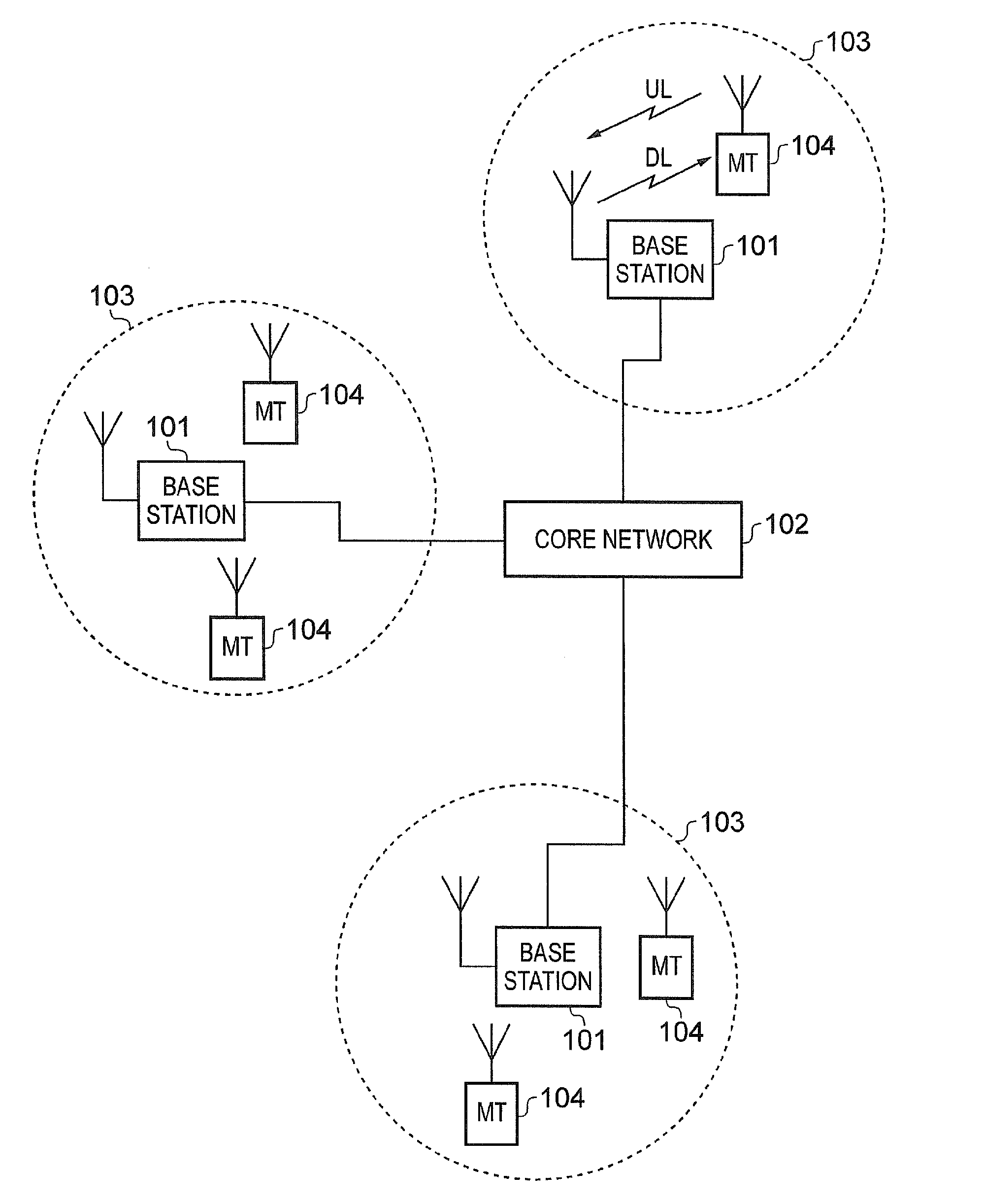
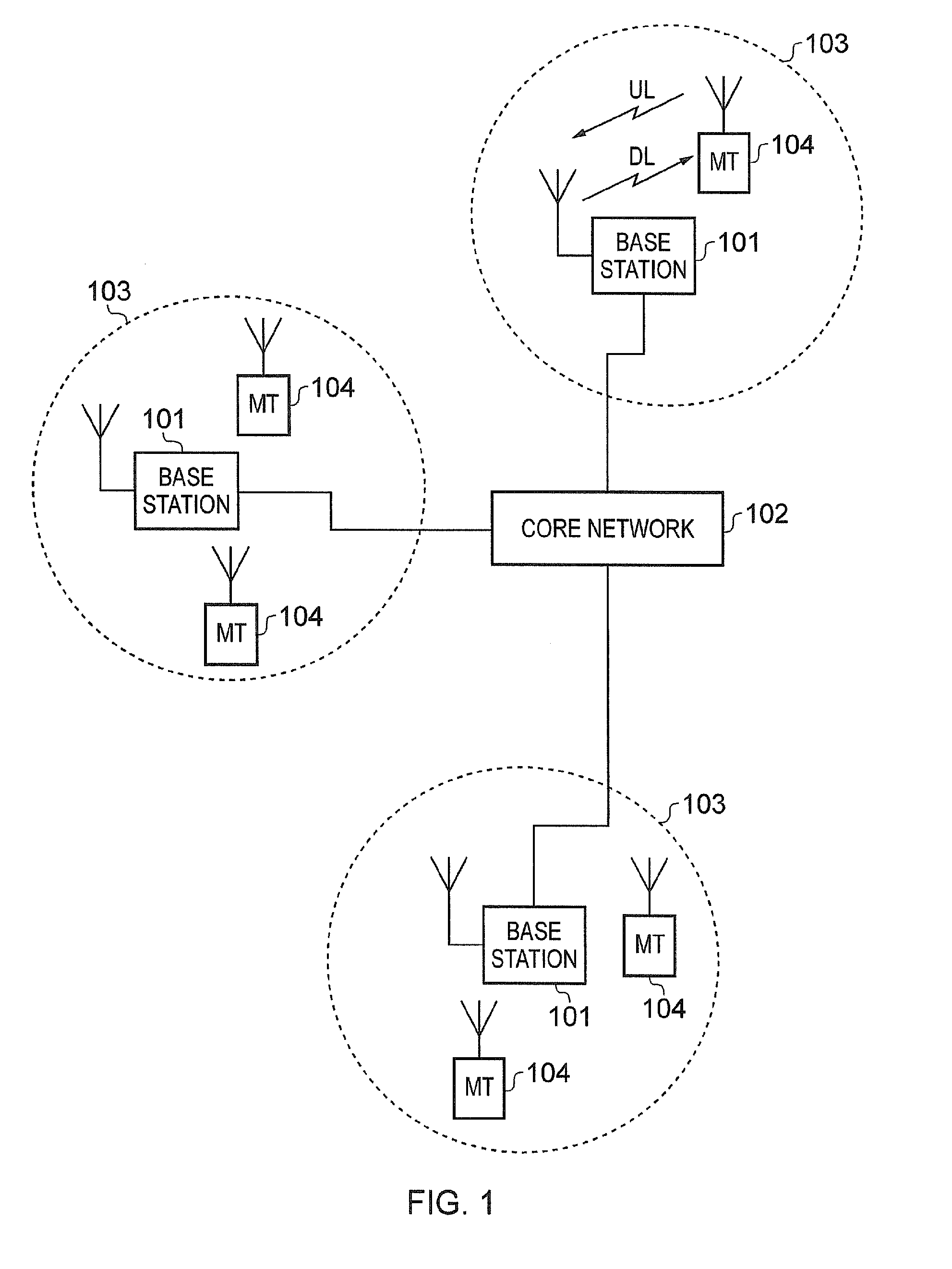
[0113]FIG. 14 provides a schematic diagram showing part of an adapted LTE mobile telecommunication system arranged in accordance with an example of the present invention. The system includes an adapted enhanced Node B (eNB) 1401 connected to a core network 1408 which communicates data to a plurality of conventional LTE terminals 1402 and reduced capability terminals 1403 within a coverage area (i.e. cell) 1404. Each of the reduced capability terminals 1403 has a transceiver unit 1405 which includes a receiver unit capable of receiving data across a reduced bandwidth and a transmitter unit capable of transmitting data across a reduced bandwidth when compared with the capabilities of the transceiver units 1406 included in the conventional LTE terminals 1402.

[0114]The adapted eNB 1401 is arranged to transmit downlink data using a sub-frame structure that includes a virtual carrier as described with reference to FIG. 5 and to receive uplink data using a sub-frame structure as described ...


PUM


Abstract

A mobile telecommunications system including mobile terminals of first type and second type configured to transmit uplink data to a network over a radio interface using plural sub-carriers. The mobile terminals of first type configured to transmit uplink data on a first group of the sub-carriers over a first bandwidth and the mobile terminals of second type configured to transmit uplink data on a second group of the sub-carriers within the first group of sub-carrier over a second bandwidth smaller than the first bandwidth. The mobile terminals of first type transmit random access request messages to a base station of the network requesting uplink radio resources on a first random access channel. The mobile terminals of second type transmit random access request messages to the base station of the network requesting uplink radio resources on a second random access channel on sub-carriers within the second sub-carrier group.

Description

TECHNICAL FIELD OF THE INVENTION[0001]The present invention relates to methods, systems and apparatus for allocating transmission resources and transmitting data in mobile telecommunication systems.BACKGROUND OF THE INVENTION[0002]Third and fourth generation mobile telecommunication systems, such as those based on the 3GPP defined UMTS and Long Term Evolution (LTE) architecture are able to support more sophisticated services than simple voice and messaging services offered by previous generations of mobile telecommunication systems.[0003]For example, with the improved radio interface and enhanced data rates provided by LTE systems, a user is able to enjoy high data rate applications such as mobile video streaming and mobile video conferencing that would previously only have been available via a fixed line data connection. The demand to deploy third and fourth generation networks is therefore strong and the coverage area of these networks, i.e. geographic locations where access to th...

Claims


Application Information

Patent Timeline
Patent Type & Authority Applications(United States)
IPC IPC(8): H04W74/08
CPCH04W74/0833H04L5/0064H04L5/0094H04L5/0053H04L5/0007H04W28/20H04W72/0453H04L5/0048
Inventor MCNAMARA, DARRENDARWOOD, PETERBEALE, MARTINLILLIE, ANDREW
Owner IPLA HLDG
Why Eureka
Try Eureka