
Fixed Blade Assembly Usable in Exhaust Pump, and Exhaust Pump Provided with same

a technology for fixing blades and exhaust pumps, which is applied in the direction of liquid fuel engines, marine propulsion, vessels, etc., can solve the problems of increasing the time required to reach the desired degree of vacuum, increasing the height of stator blades, and reducing evacuation efficiency, so as to shorten the evacuation time and improve the evacuation performance

Active Publication Date: 2014-01-09
EDWARDS JAPAN
View PDF4 Cites 2 Cited by
  • Summary
  • Abstract
  • Description
  • Claims
  • Application Information

AI Technical Summary

Benefits of technology

The present invention provides a stator blade assembly and an exhaust pump with improved evacuation performance by shortening the evacuation time. Specifically, a stator blade assembly is provided that inhibits reverse flow of gas molecules through gaps between stator blades and reduces the evacuation time. The assembly includes a stator blade base that is supported by frames and a projecting portion on the frame to prevent reverse flow. Additionally, a single-layer stator blade assembly can be used to further prevent reverse flow and improve evacuation performance. The invention also provides a configuration with release means to rapidly release gas or fluid confined in the frames, reducing the evacuation time.

Problems solved by technology

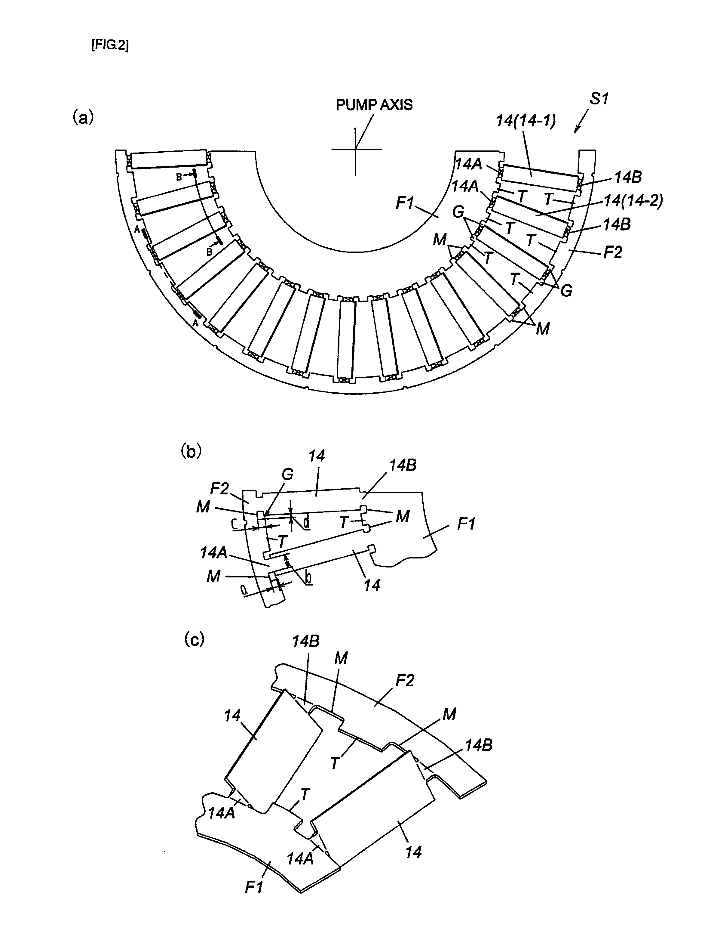
The resultant problem is that a gap unavoidably appears in the vicinity of the blade base of the stator blade (10) due to the slits (102-2, 102-3), which are necessary to perform such bending, and gas molecules flow in reverse (internal leak) through this gap, thereby increasing the time required to reach the desired degree of vacuum after the evacuation is started (referred to hereinbelow as “evacuation time”).
A problem caused by such opening of the frames (23) is that the height of the stator blades (23) becomes uneven and the decrease in evacuation efficiency caused by such unevenness increases the evacuation time.
Another problem associated with the stator blade assembly of a double-layer stacked structure such as described in Japanese Patent Publication No. 4517724 is that since the frames (23) are superimposed in the vertical direction, gas or fluid can be confined between the vertically superimposed frames (23), the gas or fluid, which has thus been confined, continuously and gradually flows out during the evacuation operation from the portion where the frames (23) are superimposed, thereby also extending the evacuation time.

Method used


Image

  • Fixed Blade Assembly Usable in Exhaust Pump, and Exhaust Pump Provided with same
  • Fixed Blade Assembly Usable in Exhaust Pump, and Exhaust Pump Provided with same
  • Fixed Blade Assembly Usable in Exhaust Pump, and Exhaust Pump Provided with same

Examples


Embodiment Construction

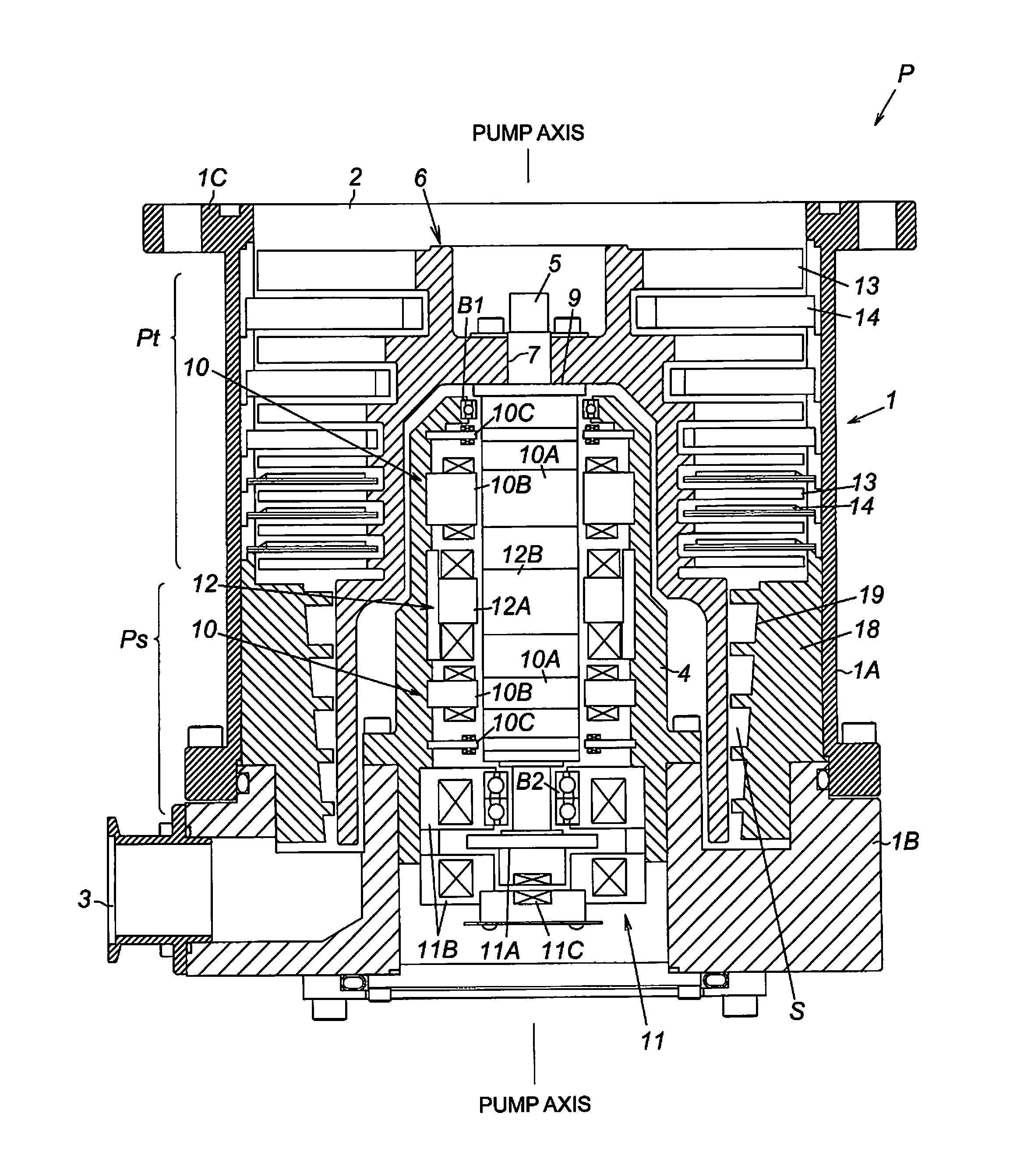
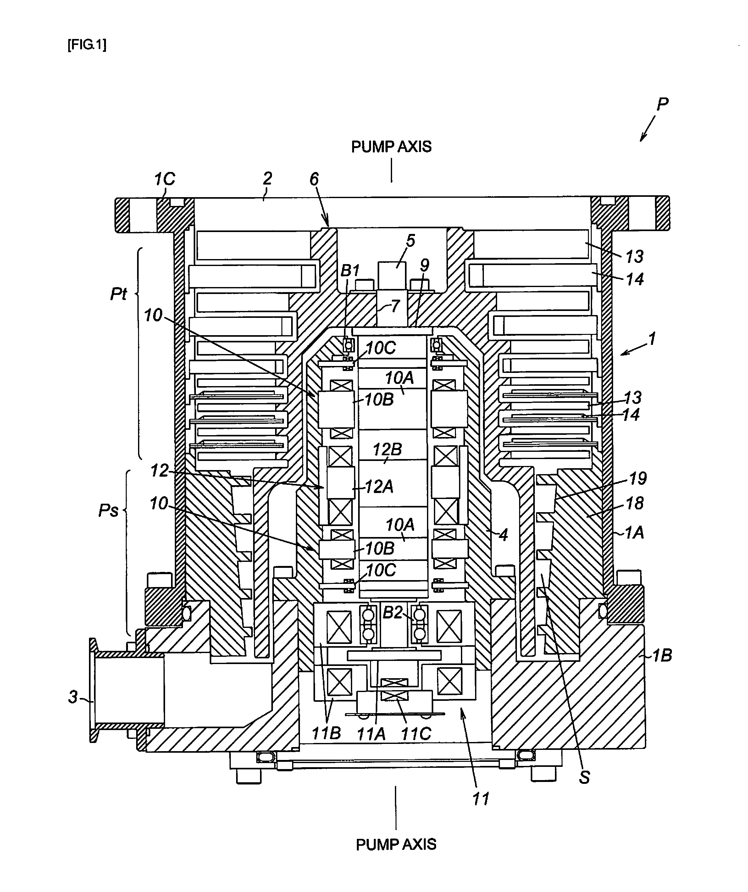
[0042]FIG. 1 is a cross-sectional view of an exhaust pump using the present invention. The exhaust pump P shown in the figure is suitable as gas evacuation means of a process chamber or other sealed chambers of a semiconductor production device, a flat panel display production device, and a solar panel production device. The exhaust pump P has a blade evacuation portion Pt that discharges gas by a rotor blade 13 and a stator blade 14, a screw slit evacuation portion Ps that discharges gas by using a screw slit 19, and a drive system therefor inside an outer case 1.

[0043]The outer case 1 has a bottomed cylindrical shape obtained by integrally connecting a tubular pump case 1A and a bottomed tubular pump base 1B with bolts in the axial direction thereof. An upper end side of the pump case 1A is opened as a gas intake port 2, and a gas evacuation port 3 is provided in a lower end side surface of the pump base 1B.

[0044]The gas intake port 2 is connected to a sealed chamber (not shown in...


PUM


Abstract

Provided are a stator blade assembly advantageous for improving the evacuation performance by shortening the evacuation time, and an exhaust pump provided with such a stator blade assembly. Inner and outer stator blade bases of a plurality of stator blades are supported by frames. A projecting portion protruding from the frame supporting the inner stator blade base, or from the frame supporting the outer stator blade base, or from both of the frames is provided in a gap in the vicinity of the inner or outer stator blade base between one of the supported stator blades and the stator blade transversely adjacent thereto.

Description

CROSS-REFERENCE TO RELATED APPLICATION[0001]This Application is a Section 371 National Stage Application of International Application No. PCT / JP2011 / 070800, filed Sep. 13, 2011, which is incorporated by reference in its entirety and published as WO 2012 / 081287 on Jun. 21, 2012, not in English, and which claims priority to Japanese Patent Application 2010-278153 filed on Dec. 14, 2010.BACKGROUND[0002]The present invention relates to a stator blade assembly usable in an exhaust pump suitable as gas evacuation means of a process chamber or other sealed chambers of a semiconductor production device, a flat panel display production device, and a solar panel production device, and also relates to an exhaust pump provided with such a stator blade assembly. More particularly, the present invention is aimed at the improvement of evacuation performance by shortening an evacuation time of the exhaust pump.[0003]A vacuum pump described, for example, in Japanese Patent Application Publication No...

Claims


Application Information

Patent Timeline
Patent Type & Authority Applications(United States)
IPC IPC(8): F01D9/02
CPCF01D9/02F04D19/042F04D29/542
Inventor SHI, YONGWEIENOMOTO, YOSHIHIRONONAKA, MANABU
Owner EDWARDS JAPAN
Learn More