Porous bone reinforcements

a technology of porous bone and reinforcement, applied in the field of porous bone reinforcement, can solve the problems of loss of bone, poor long-term outcomes for patients, limitations and problems of each of these techniques, and achieve the effect of facilitating reaming

Active Publication Date: 2014-01-09
HOWMEDICA OSTEONICS CORP
View PDF6 Cites 2 Cited by
  • Summary
  • Abstract
  • Description
  • Claims
  • Application Information

AI Technical Summary

Benefits of technology

[0018]If a cylindrical piling is used a surgical technique would include providing adequate exposure to gain a straight line access to the posterior column. A trochanteric osteotomy will facilitate this. The bed is prepared for the acetabular shell component by sequentially reaming up in size to span the dimension between the anterior and posterior columns. An acetabular shell trial is used to ascertain fit of the chosen implant size and to target and mark positions for placement of pilings. The length is measured such that the piling will protrude from the bone to contact the outer surface of the acetabular trial. The shell trial is removed. The sciatic notch is referenced to position the guide wire drill guide tool. A hole is drilled for the guide wire through the positioned jig. Image intensification is used to ascertain position of guide wire in all planes. The guide wire penetration depth is measured to select the appropriate length of piling that will be embedded in the bone. Added to that is the length of the piling that will protrude from the bone to contact the acetabular component (if that function is desired). These two measures together will guide the selection of the appropriate length piling. The acetabular is sequentially prepared for the piling with a guided reamer to establish the definitive size based on resistance to preparation from surrounding cortico-cancellous bone. To facilitate reaming, sequential preparation with shortened cutters, placed over the guide wire, can be utilized. The appropriate piling outer diameter is chosen based on line-to-line reamer preparation.
[0019]It may be desired to have the pylons make intimate contact with the acetabular shell implant. This is facilitated through the use of a tamp that matches the outer diameter of the chosen acetabular shell. The pilings are placed in the prepared site and impacted with the appropriate tamp until fully seated. Multiple pilings can be impacted simultaneously with the use of the tamp. The acetabular shell is then impacted to fit within reamed AP columns and against pilings.

Problems solved by technology

Revision hip surgery poses many challenges for the orthopedic surgeon and is sometimes associated with poorer long term outcomes for the patient than primary surgery.
One such challenge is related to the loss of bone that results from the erosion of bone that is caused by a loosened primary implant and / or the process of removing the initial implant.
Each of these techniques have limitations and problems.
Autograft bone is in limited supply and often difficult to harvest creating comorbidities for the patient.
Allograft bone is expensive and may or may not incorporate with the host and poses the potential for an immune response by the patient.
On the other hand, custom prostheses are expensive, inexact, owing to limitations with pre-operative imaging and design.
Augments, like custom prosthesis, may not fit precisely and present additional bulk that can irritate soft tissue and are challenged with having adequate host bone support themselves.
Surgical placement of these relatively bulky implants is often complicated and requires extensive undesirable patient exposure.
Fixation is difficult to achieve and this rather bulky implant invades soft tissue space.

Method used


Image

  • Porous bone reinforcements
  • Porous bone reinforcements
  • Porous bone reinforcements

Examples


Embodiment Construction

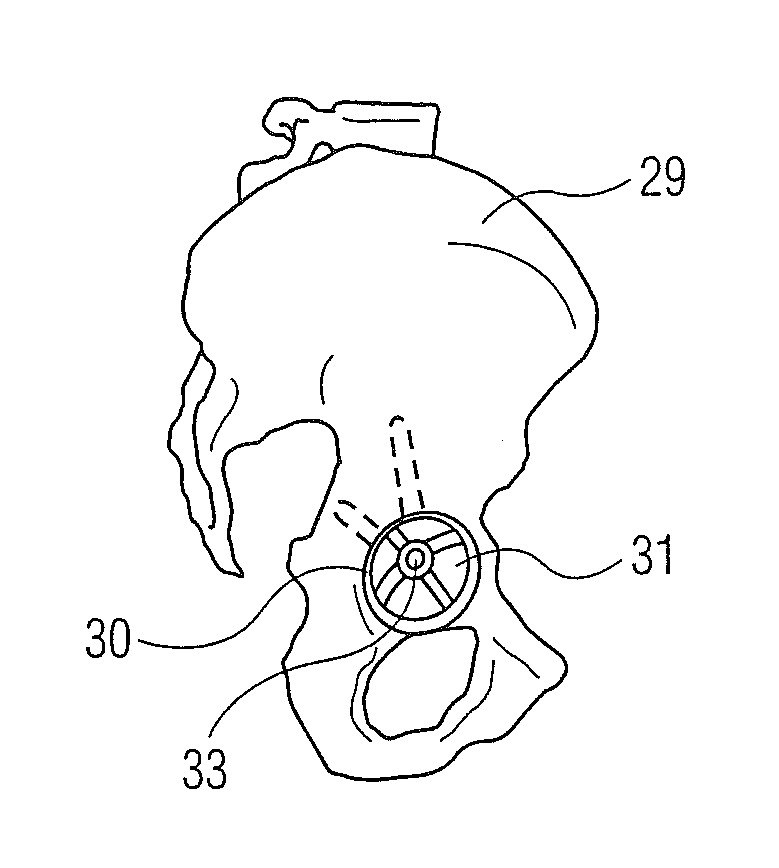
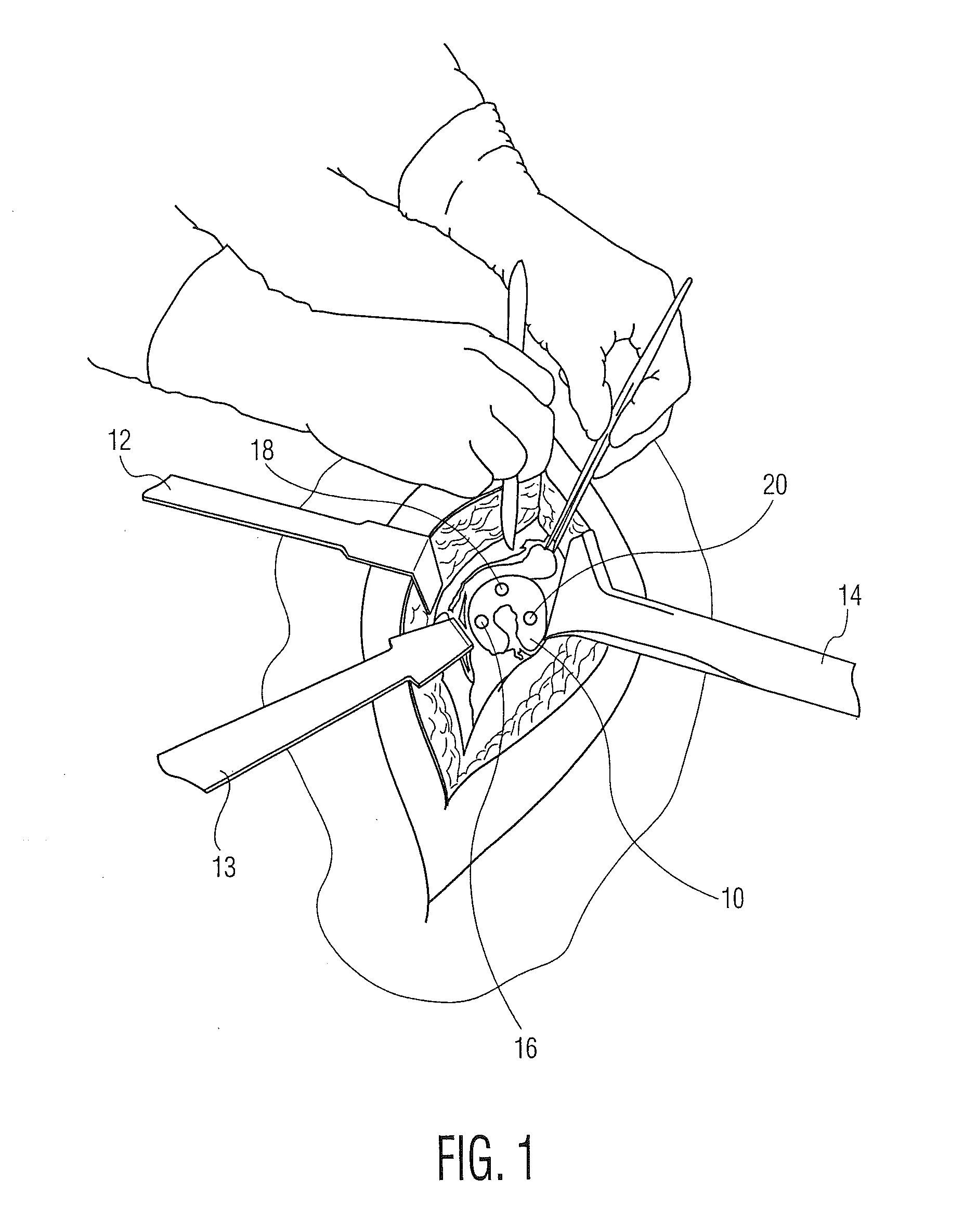
[0032]Referring to FIG. 1 there is shown a surgeon exposing an acetabulum 10 for preparing the acetabulum to receive a typical acetabular implant (not shown). After making an incision retractors 12, 13, and 14 are utilized to keep the incision open while the surgeon prepares the acetabulum. Also indicated in FIG. 1 are three locations 16, 18 and 20 for placing the reinforcement pilings or pins of the present invention.

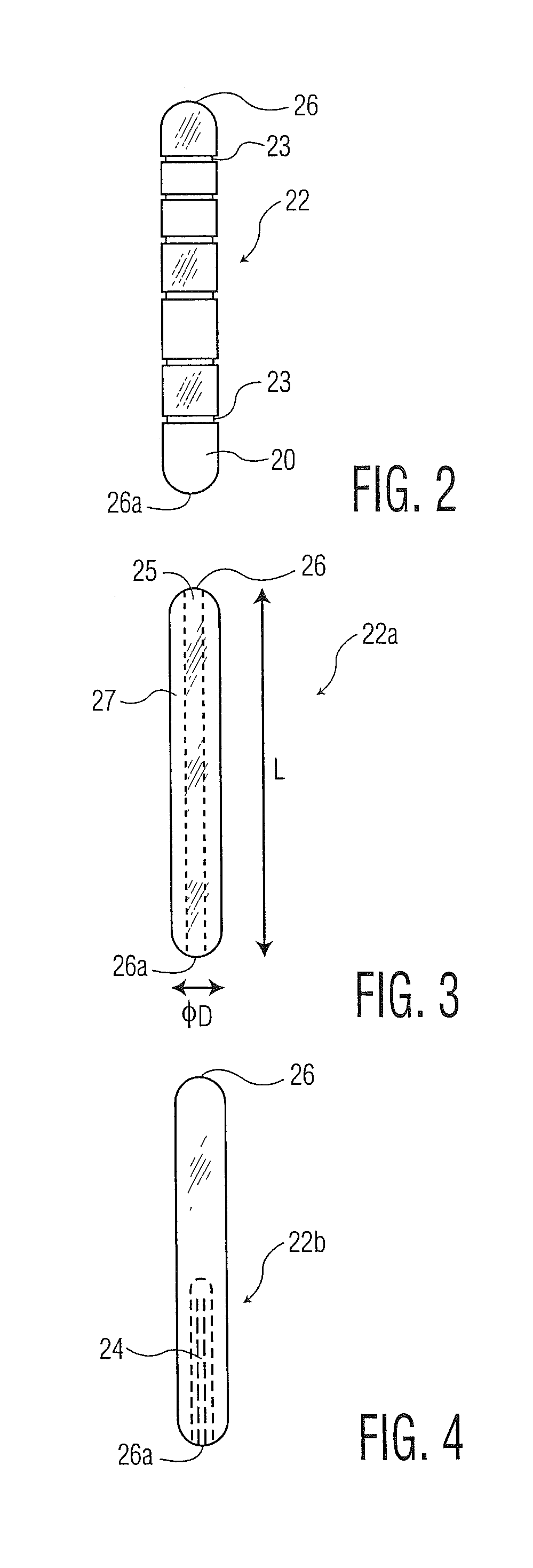
[0033]Referring to FIGS. 2-4 there is shown three embodiments of the reinforcement pilings or pins of the present invention generally denoted as 22, 22a and 22b respectively. Referring to FIG. 2 there is shown a piling or pin 22 made of solid metal such as titanium, stainless steel or cobalt chrome alloy for insertion into the acetabulum. The pin has a cylindrical shape with a diameter of 10 to 30 mm and a length of between 25 and 125 mm. The pin may have a series of spaced circumferential grooves 23 to provide for greater retention of the pin or piling 22 in the bone ...


PUM


Abstract

A method of reinforcing the bone in an acetabulum for receiving a prosthetic acetabular implant includes preparing a surface of the acetabulum to receive an acetabular implant. At least one porous generally cylindrical bone reinforcement element is provided. At least one bore is drilled in an area of the acetabulum receiving the prosthetic acetabular implant for receiving at least one and preferably more reinforcement elements in the form of cylindrical pilings. The cylindrical porous bone reinforcement element is inserted in the bore such that an exposed surface of the porous bone reinforcement element is adjacent the surface of the acetabulum. The acetabular implant is then implanted with an outer surface of the acetabular implant supported by the reinforcement members.

Description

BACKGROUND OF THE INVENTION[0001]Revision hip surgery poses many challenges for the orthopedic surgeon and is sometimes associated with poorer long term outcomes for the patient than primary surgery. One such challenge is related to the loss of bone that results from the erosion of bone that is caused by a loosened primary implant and / or the process of removing the initial implant.[0002]As is the case for primary surgery, the durability of implant fixation relies on the ability of the host bone to support the prosthesis over the longer term. In revision surgery, the host bone may be compromised and it is incumbent upon the surgeon to recreate a supportive bed for the revision prosthesis. Common techniques that are used to achieve this include bone grafting (autograft and allograft), the use of custom designed prosthesis that intend to fill the space once occupied by host bone and by adding shaped implant augments to a standard implant such as, for example, an acetabular cup.[0003]Ea...

Claims


Application Information

Patent Timeline
Patent Type & Authority Applications(United States)
IPC IPC(8): A61F2/34A61B17/17
CPCA61F2/34A61B17/1746A61B17/68A61B17/846A61B17/866A61F2/30734A61F2/30749A61F2002/30011A61F2002/30112A61F2002/30205A61F2002/30433A61F2002/30736A61F2002/30822A61F2002/3092A61F2002/30962A61F2002/3412
Inventor POGGIE, MATTHEW P.HEDLEY, ANTHONY K.GUANG DONG, NICHOLAS NAI
Owner HOWMEDICA OSTEONICS CORP
Why Eureka
Try Eureka