
Systems and methods for balancing an electrical grid with networked buildings

a technology of electrical power grid and networked buildings, applied in the direction of computer control, process and machine control, instruments, etc., can solve the problems of computational cost and inapplicability of existing simulation methods and tools, and achieve the effect of reducing the energy optimization level of at least one building and reducing the energy optimization level

Inactive Publication Date: 2014-01-09
OPTIMUM ENERGY
View PDF14 Cites 15 Cited by
  • Summary
  • Abstract
  • Description
  • Claims
  • Application Information

AI Technical Summary

Benefits of technology

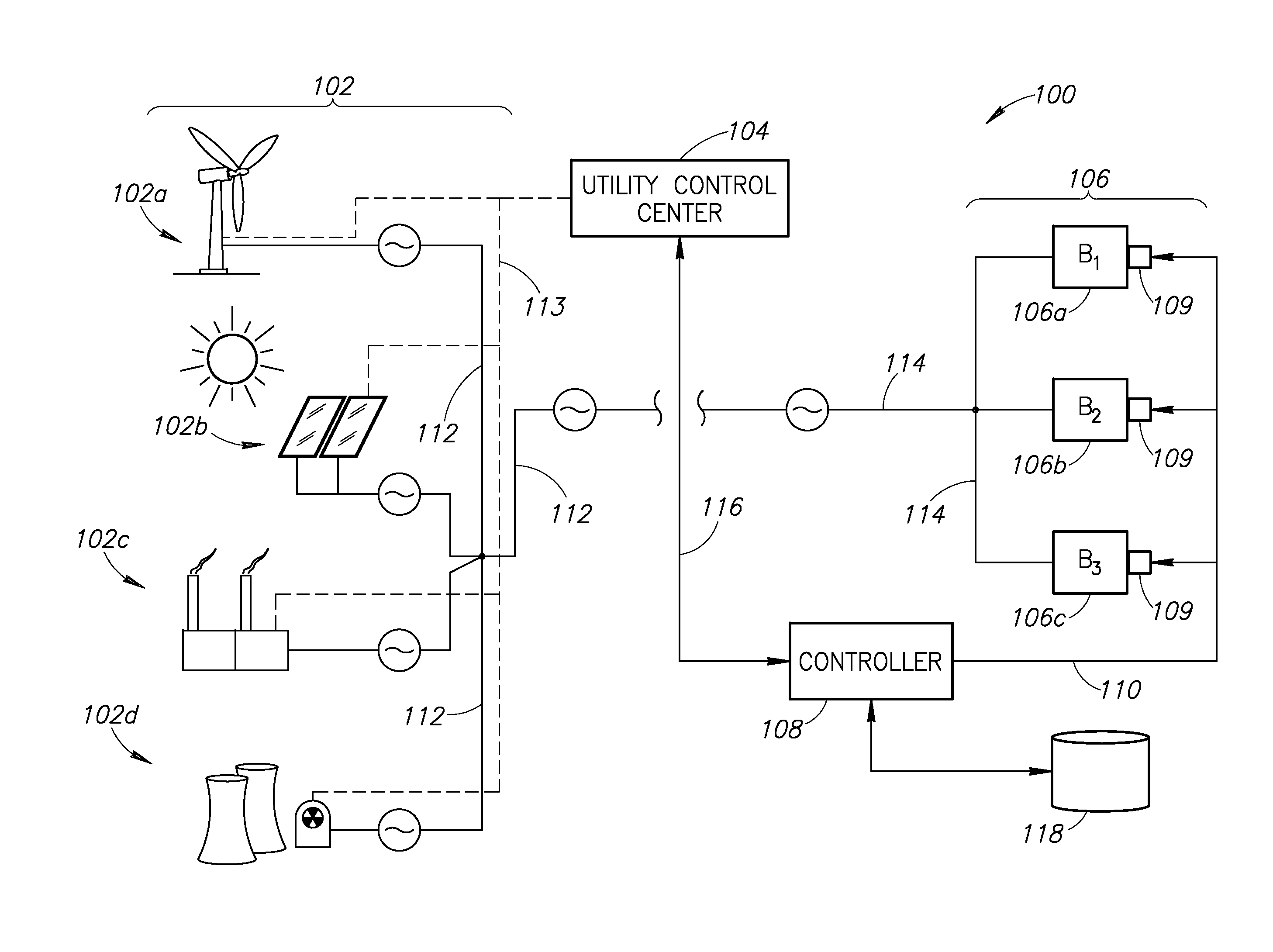
This patent describes a system and method for controlling multiple buildings that are connected to an electric power grid. The system includes a control center that receives information about the amount of power being supplied, and each building has a controller that communicates with the control center. The controller also communicates with other controllers of other buildings. The system can compare the amount of power supplied to the demand load of each building and instruct its controller to reduce its energy optimization level for a period of time if the total power supply exceeds the demand. The technical effect of this patent is to provide a more efficient and effective way to manage energy usage in a network of buildings.

Problems solved by technology

Conventionally, local power grids have been manually controlled and for various reasons have been susceptible to “brown outs,” which is understood to be a reduction or cutback in electric power because of a power generation shortage, a mechanical failure, or unanticipated load requirements by the power consumers.
Unfortunately, existing simulation methods and tools are computationally very costly and therefore not suitable for a standard embedded building controller.

Method used


Image

  • Systems and methods for balancing an electrical grid with networked buildings
  • Systems and methods for balancing an electrical grid with networked buildings
  • Systems and methods for balancing an electrical grid with networked buildings

Examples


Embodiment Construction

[0019]In the following description, certain specific details are set forth in order to provide a thorough understanding of various embodiments of the invention. However, one skilled in the art will understand that the invention may be practiced without these details. In other instances, well-known structures associated with electrical power grids, which may include smart grid systems, HVAC systems, utility control centers, transmission or power lines, building automation controllers, communication networks, various computing and / or processing systems, various HVAC system operational parameters, and methods of operating any of the above with respect to one or more buildings have not necessarily been shown or described in detail to avoid unnecessarily obscuring descriptions of the embodiments of the invention.

[0020]In one embodiment of the present invention, an electrical power grid having multiple, networked buildings and one or more power sources may be balanced to minimize ineffici...


PUM


Abstract

An electrical power grid includes multiple, networked buildings that receive electrical power from one or more power generation sources. A networking control system communicates with a utility control center to obtain information regarding the amount of power being supplied by the power generation sources. The networking control system further obtains information from one or more building automation controllers that are controllably associated with a plurality of networked buildings. The networking control system determines whether the total amount of power being supplied exceeds a total demand load for the plurality of buildings. And if so, the networking control system commands one or more of the building automation controllers to operate one ore more of the buildings a reduced energy efficiency level, which may take the form of an optimization curve.

Description

FIELD OF THE INVENTION[0001]The present invention generally relates to systems and methods for balancing an electrical power grid with networked buildings, and more specifically to systems and methods for controlling an energy optimization level of the networked building with a network control system.BACKGROUND OF THE INVENTION[0002]An electric grid is a network of synchronized power providers and consumers connected by transmission and distribution lines and operated by one or more utility control centers. In common parlance, the phrasepower grid” generally refers to a transmission system for electricity. In the continental United States, there are three primary grids: the Eastern Interconnect, the Western Interconnect and the Texas Interconnect. In Alaska and Hawaii, several smaller systems interconnect parts of each state.[0003]On a local or regional level, a local power grid may take the form of one or more power generation sources, various power transmission lines, and power ...

Claims


Application Information

Patent Timeline
Patent Type & Authority Applications(United States)
IPC IPC(8): G05F5/00
CPCG05F5/00Y02B70/3225Y04S20/222Y04S20/242H02J3/001H02J2310/14H02J3/14Y02B70/30G05B15/02H02J3/38Y02B10/10Y02E10/56Y02E10/76H02J2300/28
Inventor DEMPSTER, IAN
Owner OPTIMUM ENERGY
Learn More