
Multi-component electromagnetic prospecting apparatus and method of use thereof

a multi-component, electromagnetic prospecting technology, applied in the direction of gravity wave measurement, geological measurement, reradiation, etc., can solve the problems of stringent accuracy requirements, never implemented successfully, increase the cost of surveying, etc., to achieve effective focus of electromagnetic signal, improve signal to noise ratio and potential depth, and improve sensitivity

Inactive Publication Date: 2014-01-09
LAURENTIAN UNIV OF SUDBURY
View PDF51 Cites 100 Cited by
  • Summary
  • Abstract
  • Description
  • Claims
  • Application Information

AI Technical Summary

Benefits of technology

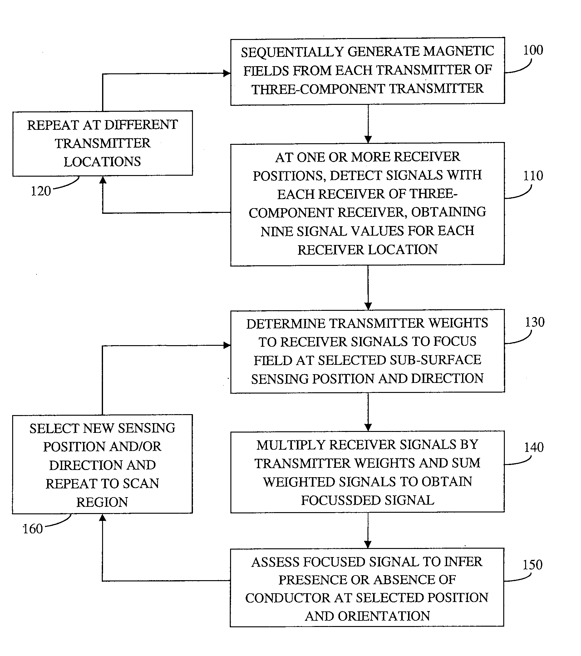
The patent describes a method of using a three-component transmitter for electromagnetic prospecting. This transmitter can be coupled to targets in the subsurface from any orientation. By combining responses from multiple locations, an array of multiple transmitters and receivers can be formed, improving the signal to noise ratio and the potential depth that the system can sense. This array can effectively focus the electromagnetic signal at a specific location, increasing sensitivity.

Problems solved by technology

The weakness of the large loop configuration is that the magnetic field vector at any point in the ground only points in one orientation.
Each additional large loop takes time to lay-out and thus increases the cost of the survey.
One of the difficulties in doing this is that the response from the highly conductive body has a waveform that is identical to the waveform coming from the transmitter.
Bucking coils have been proposed for non-rigid systems (Puranen and Kahma, U.S. Pat. No. 2,741,736), but never implemented successfully as it is labourious, time consuming and costly (Robinson, Canadian Patent 854344).
This approach is used successfully with ground or borehole EM systems (West et al., 1984; Smith and Balch, 2000), but not with airborne systems due to the very stringent accuracy requirement.
However, this system was never demonstrated to work in practice.
However, this method is also insensitive to extremely good conductors, as the distortion of the in-phase response from the extremely good conductor will essentially be identical at both frequencies.
In addition, compared with the size of the targets and the size and position of the receivers, these UXO transmitters could not be considered as dipoles.
Unfortunately, the aforementioned systems for detecting extremely good conductors are limited by their requirement for maintaining and controlling a fixed spatial relationship between the transmitter and receiver and often lack sensitivity in detecting highly conductive bodies.
Also, the profiling methods used for EM prospecting are limited in their depth penetration and the large loop methods require that the coupling of the transmitter to the target in the subsurface be known.

Method used


Image

  • Multi-component electromagnetic prospecting apparatus and method of use thereof
  • Multi-component electromagnetic prospecting apparatus and method of use thereof
  • Multi-component electromagnetic prospecting apparatus and method of use thereof

Examples


Embodiment Construction

[0062]As required, embodiments of the present invention are disclosed herein. However, the disclosed embodiments are merely exemplary, and it should be understood that the invention may be embodied in many various and alternative forms. The Figures are not to scale and some features may be exaggerated or minimized to show details of particular elements while related elements may have been eliminated to prevent obscuring novel aspects. Therefore, specific structural and functional details disclosed herein are not to be interpreted as limiting but merely as a basis for the claims and as a representative basis for teaching one skilled in the art to variously employ the present invention. For purposes of teaching and not limitation, the illustrated embodiments are directed to a multi-component electromagnetic prospecting apparatus and methods of detecting subsurface conductive bodies.

[0063]As used herein, the terms, “comprises” and “comprising” are to be construed as being inclusive and...


PUM


Abstract

Systems and methods are provided for the detection of conductive bodies using three-component electric or magnetic dipole transmitters. The fields from multiple transmitters can be combined to enhance fields at specific locations and in specific orientation. A one- two- or three-component receiver or receiver array is provided for detecting the secondary field radiated by a conductive body. The data from multiple receivers can be combined to enhance the response at a specific sensing location with a specific orientation. Another method is provided in which a three-component transmitter and receiver are separated by an arbitrary distance, and where the position and orientation of the receiver relative to the transmitter are calculated, allowing the response of a highly conductive body to be detected.

Description

FIELD OF THE INVENTION[0001]This invention relates to electromagnetic prospecting methods. More particularly, this invention relates to methods of electromagnetic prospecting for conductive bodies.BACKGROUND OF THE INVENTION[0002]Controlled source electromagnetic (EM) systems have been used for many years for prospecting for minerals (Grant and West, 1965; Nabighian, 1991). In more recent years, they have also been used for groundwater investigations, environmental investigations (Ward, 1990), the detection of unexploded ordnance (e.g., Billings et al., 2010) and more recently in agricultural mapping (Lück and Müller, 2009). Electromagnetic systems have also been used in resistivity logging tools (Wang et al., 2009; Davydycheva, 2010a; 2010b) and in seafloor controlled source electromagnetic (CSEM) systems (Chave and Cox, 1982; Cheesman et al., 1987; 1988; MacGregor and Sinha, 2000; Ellingsrud et al., 2002; and Constable and Srnka, 2007).[0003]These controlled source EM systems comp...

Claims


Application Information

Patent Timeline
Patent Type & Authority Applications(United States)
IPC IPC(8): G01V3/08
CPCG01V3/08G01V3/12
Inventor SMITH, RICHARD
Owner LAURENTIAN UNIV OF SUDBURY
Learn More