Pneumatic clutch with improved capacity and longevity

a technology of pneumatic fan and clutch, applied in the direction of fluid actuated clutch, clutch, non-mechanical actuated clutch, etc., can solve the problems of heat also being exhausted to the atmosphere, longer path, etc., and achieve the effect of reducing the amount of heat generated during use, increasing capacity and durability, and not significantly increasing the size or shap

Active Publication Date: 2014-01-16
BORGWARNER INC
View PDF5 Cites 4 Cited by
  • Summary
  • Abstract
  • Description
  • Claims
  • Application Information

AI Technical Summary

Benefits of technology

[0008]It is therefore an object to the present invention to provide a clutch assembly with increased capacity and durability and without significantly increasing its size or shape. It is further an object of the present invention to provide a clutch assembly which internalizes a smaller amount of the heat generated during use, and which is less expensive and easier to manufacture and assemble.

Problems solved by technology

Some heat will still be internalized in the clutch, but the path is longer and some of the heat will also be exhausted to the atmosphere.

Method used


Image

  • Pneumatic clutch with improved capacity and longevity
  • Pneumatic clutch with improved capacity and longevity
  • Pneumatic clutch with improved capacity and longevity

Examples


Embodiment Construction

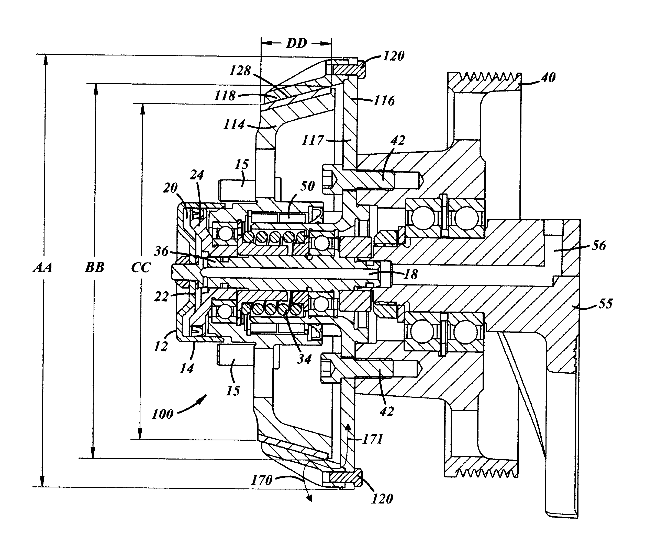
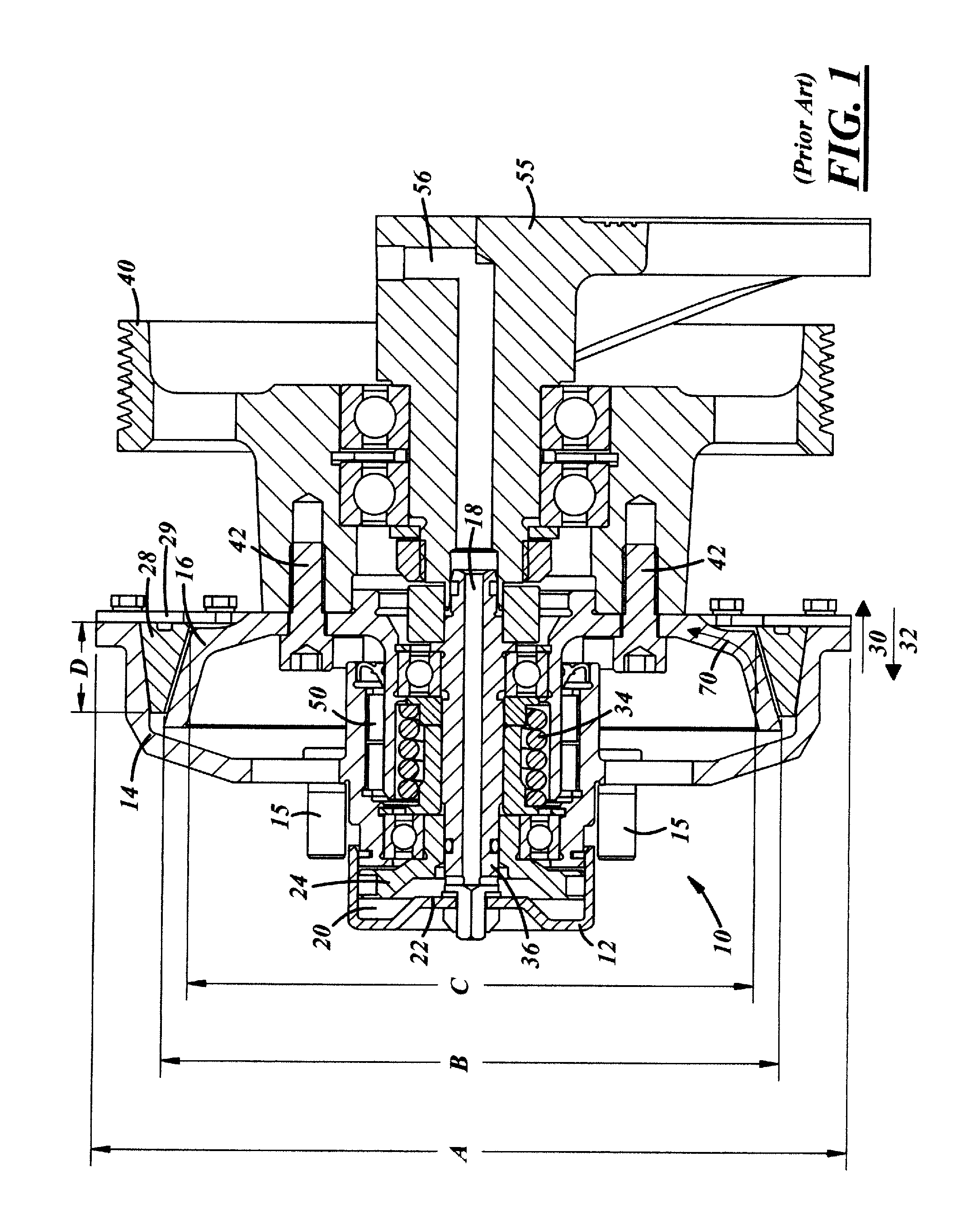
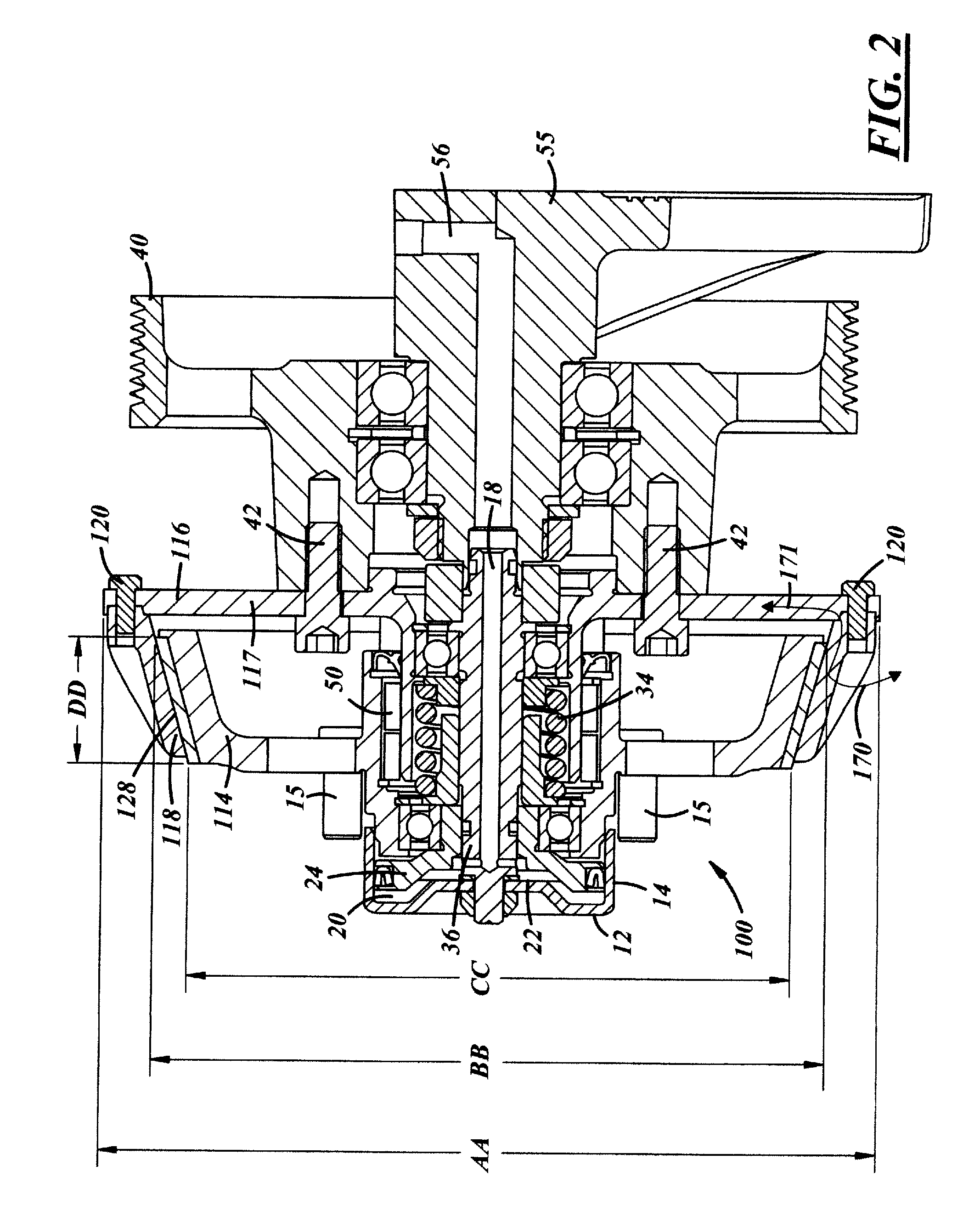
[0018]FIG. 1 depicts a cone clutch fan drive assembly 10 of a type known in the industry. The fan drive assembly 10 includes a clutch assembly 12 having a clutch housing 14. The present invention provides novel and valuable improvements to such clutch assemblies that provides increased torque, capacity, and durability, as well as less heat buildup, without significantly changing the exterior size and configuration of the assembly.

[0019]The components and operation of the clutch assembly 12 are similar to the clutch assemblies shown and described in U.S. patent application Ser. No. 10 / 905,505 entitled “Reduced Axial Length Air Actuated Cone Clutch Fan Drive,” now abandoned, and U.S. Pat. No. 7,731,006. Thus, many of the components contained in the clutch assembly utilized herewith, as well as the basic operation thereof, do not need to be discussed and reference is made to these two references for a further discussion and description of them.

[0020]The clutch actuating assembly 12 inc...


PUM


Abstract

Pneumatic fan drive assembly with improved capacity, longevity and heat control. The output member is positioned radially internally of the output member. The friction mechanism has longer movement (moment) arms and torque. The friction engagement has an increased friction surface arm. A portion of the heat generated by the friction mechanism is evacuated to the atmosphere rather than being completely internalized in the assembly. The friction material for the friction lining alternatively can be formed of a plasma spray.

Description

CROSS REFERENCE TO RELATED APPLICATIONS[0001]This application claims the benefit of U.S. Provisional Application Ser. No. 61 / 669,673, filed Jul. 10, 2012, which is incorporated herein by reference in its entirety.TECHNICAL FIELD[0002]The present invention relates generally to a pneumatic fan clutch and more particularly to a fan clutch which has improved capacity and longevity.BACKGROUND OF THE INVENTION[0003]Vehicle engines commonly utilize cooling assemblies to remove excess heat from the engine and maintain an optimal operating temperature. The cooling assembly pumps a coolant through the engine and other components in order to control engine temperature. Heat generated within the engine and other components is absorbed by the coolant and dispersed into the surrounding atmosphere through the use of a radiator. In order to improve dispersal by the radiator, it is common to utilize fan assemblies to draw or force air past the radiator to assist in temperature transmission.[0004]It ...

Claims


Application Information

Patent Timeline
Patent Type & Authority Applications(United States)
IPC IPC(8): F16D25/0632
CPCF16D25/0632
Inventor SETTINERI, SAMUEL E.TEMBREULL, VINCENT M.
Owner BORGWARNER INC
Why Eureka
Try Eureka