Millimeter waveband filter and method of increasing rejection band attenuation

a filter and millimeter waveband technology, applied in the field of filters, can solve the problems of manufacturing difficulty at a frequency over 100 ghz, difficulty in strict measurement of unnecessary emission or the like, and inability to separate harmonics, etc., and achieve the effect of increasing the attenuation of the rejection band, serious affecting the passband characteristics of the filter, and high selection characteristics

Active Publication Date: 2014-01-16
ANRITSU CORP
View PDF6 Cites 1 Cited by
  • Summary
  • Abstract
  • Description
  • Claims
  • Application Information

AI Technical Summary

Benefits of technology

[0030]As described above, since a structure in which a resonator formed by a pair of electric wave half mirrors is provided in a continuous transmission line allowing transmission only in a TE10 mode is made, a special device for inputting plane waves is not required, and the electric wave half mirrors do not need to transmit plane waves and may have an arbitrary shape.
[0031]The filter is of a closed type as a whole, and thus there is no loss by emission to the external space in principle. Therefore, very high selection characteristics can be realized in the millimeter waveband.
[0032]The high-pass filter is formed in the transmission line between the end of the waveguide and the electric wave half mirror so as to have the cutoff frequency matching the upper limit of the lower rejection band of the filter passband, whereby it is possible to significantly increase the attenuation of the rejection band lower than the filter passband without seriously affecting the passband characteristics of the filter.
[0033]The choke groove provided in the inner wall of the high-pass filter forms the band rejection filter which inhibits the passage of electromagnetic waves of the higher rejection band, whereby it is possible to significantly increase the attenuation of the rejection band higher than the filter passband without seriously affecting the passband characteristics of the filter.

Problems solved by technology

In the conventional measurement technologies, it is not possible to separate harmonics of local oscillation from the measurement result, and there is difficulty in strict measurement of unnecessary emission or the like.
Meanwhile, manufacturing gets difficulty at a frequency over 100 GHz.

Method used


Image

  • Millimeter waveband filter and method of increasing rejection band attenuation
  • Millimeter waveband filter and method of increasing rejection band attenuation
  • Millimeter waveband filter and method of increasing rejection band attenuation

Examples


Embodiment Construction

[0042]Hereinafter, an embodiment of the invention will be described referring to the drawings.

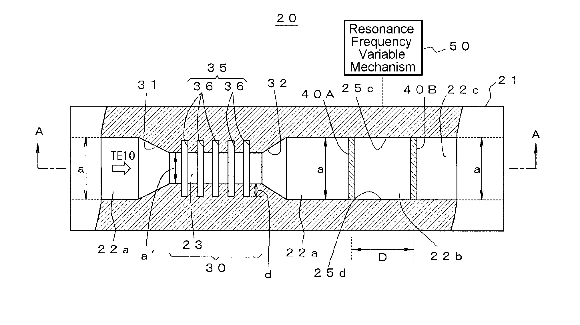
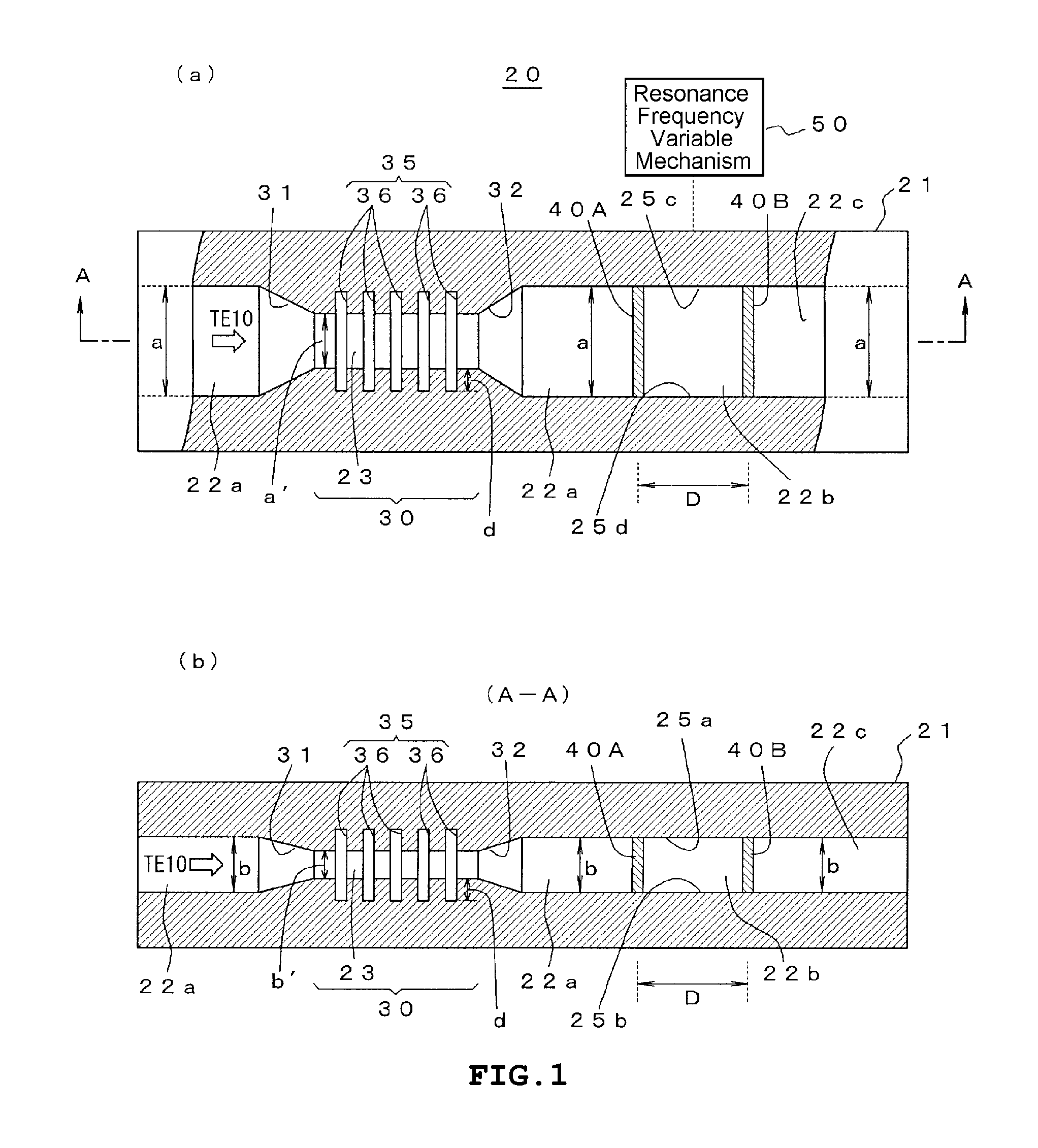
[0043]FIGS. 1A and 1B show the basic structure of a millimeter waveband filter 20 according to the invention.

[0044]As shown in a side view of FIG. 1A, the millimeter waveband filter 20 has a waveguide 21, a pair of electric wave half mirrors 40A and 40B, and a resonance frequency variable mechanism 50 as a resonance frequency variable means.

[0045]The waveguide 21 has a hollow rectangular column, and a transmission line 22 which has a rectangular sectional shape and is of size (for example, standard size a×b=2.032 mm×1.016 mm) allowing electromagnetic waves in a predetermined frequency range (for example, 110 to 140 GHz) of a millimeter waveband to propagate only in a TE10 mode is formed continuously from one end to the other end excluding a portion corresponding to a high-pass filter 30 described below.

[0046]In the waveguide 21, a pair of electric wave half mirrors 40A and 40B which have ch...


PUM


Abstract

A millimeter waveband filter is provided with a resonator formed by a pair of electric wave half mirrors in a transmission line of a waveguide allowing electromagnetic waves in a predetermined frequency range of a millimeter waveband to propagate in a TE10 mode, and allows frequency components centering on the resonance frequency of the resonator to pass therethrough. A high-pass filter which has a transmission line reduced in size so as to have a cutoff frequency matching an upper limit of a lower rejection band of a filter passband is formed in a transmission line between the end of the waveguide and the electric wave half mirror, thereby increasing the attenuation of the lower rejection band.

Description

TECHNICAL FIELD[0001]The present invention relates to a filter which is used in a millimeter waveband.BACKGROUND ART[0002]In recent years, there is an increasing need for the use of electric waves in response to a ubiquitous network society, and a wireless personal area network (WPAN) which realizes wireless broadband at home or a millimeter waveband wireless system, such as a millimeter-wave radar, which supports safe and secure driving starts to be used. An effort to realize a wireless system at a frequency equal to or greater than 100 GHz is actively made.[0003]In regard to second harmonic evaluation of a wireless system in a 60 to 70 GHz band or evaluation of a radio signal in a frequency band equal to or greater than 100 GHz, as the frequency becomes high, the noise level of a measurement device and conversion loss of a mixer increase and frequency precision is lowered. For this reason, a high-sensitivity and high-precision technology of a radio signal over 100 GHz has not been...

Claims


Application Information

Patent Timeline
Patent Type & Authority Applications(United States)
IPC IPC(8): H01P1/20
CPCH01P1/20H01P1/162H01P1/2082
Inventor KAWAMURA, TAKASHIOTANI, AKIHITO
Owner ANRITSU CORP
Why Eureka
Try Eureka