Error correction device

Active Publication Date: 2014-01-16
DENSO CORP
View PDF3 Cites 5 Cited by
  • Summary
  • Abstract
  • Description
  • Claims
  • Application Information

AI Technical Summary

Benefits of technology

[0010]A plurality of the correction pulse signals is inserted into a series of modulated pulse signals transmitted from the modulation section. In general, noise is added to the correction pulse signals in addition to the modulated pulse signals on the transmission path. Such noise often causes detection error. In particular, regardless of a pulse width of a pulse signal, the pulse width of the pulse signal is changed to a constant value by the error caused by noise occurring on the transmission path including a photocoupler as an opto-isolator. It is accordingly possible to calculate a magnitude of the error, caused by n

Problems solved by technology

In general, when noise is added to the pulse signals on the pulse signal transmission path to which the photocoupler is mounted, such noise added into the pulse signals often cause the microcomputer to decrease a detection accuracy of the temperature of the detection target.
Various types of physical property value detection devices have the above problem of decreasing or deterioration of the detection accuracy

Method used


Image

  • Error correction device
  • Error correction device
  • Error correction device

Examples


Example

First Exemplary Embodiment

[0026]A description will be given of an error correction device according to a first exemplary embodiment which is used in a vehicle equipped with an electric rotary machine as a main drive machine with reference to FIG. 1 to FIG. 9.

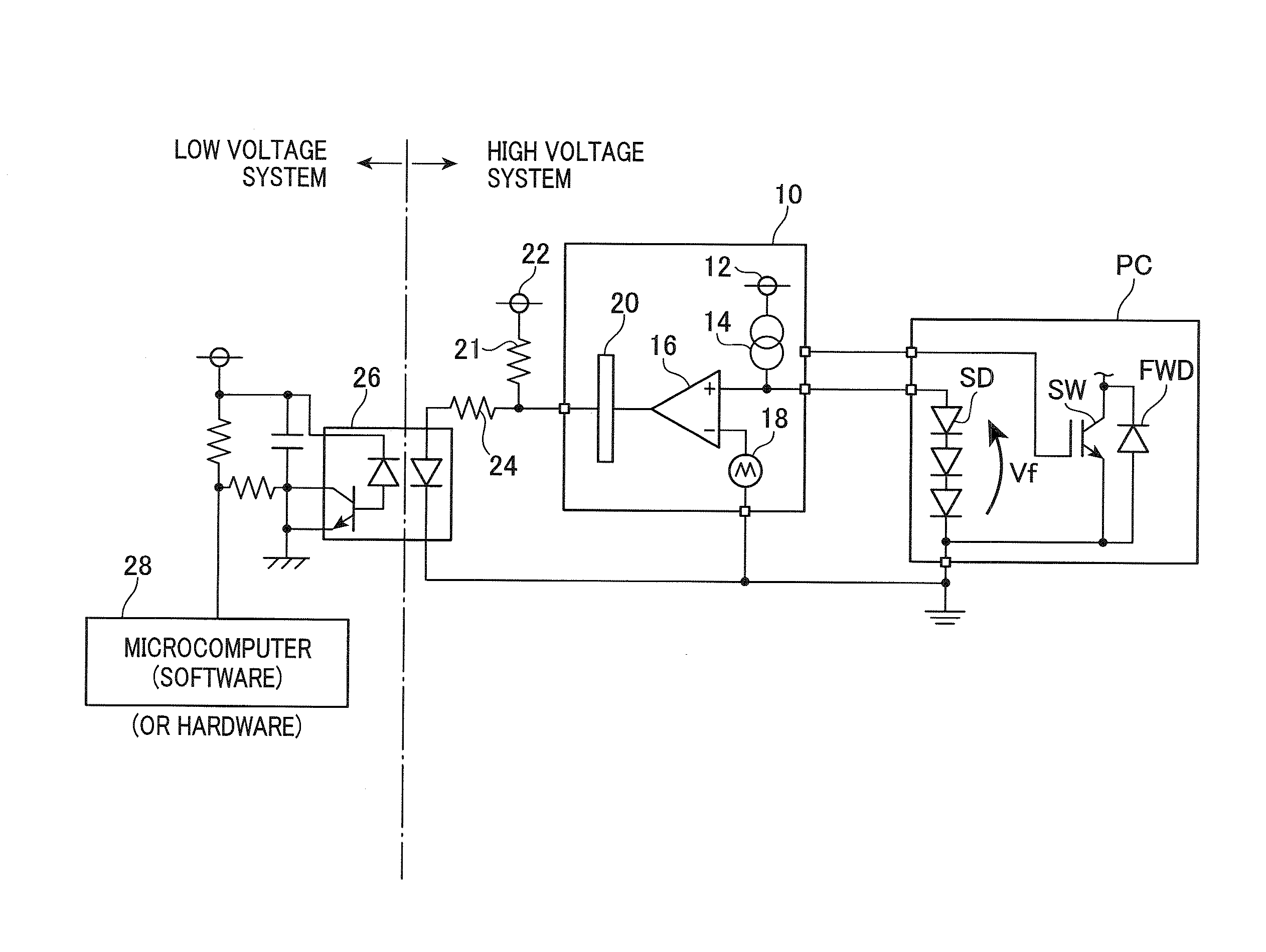
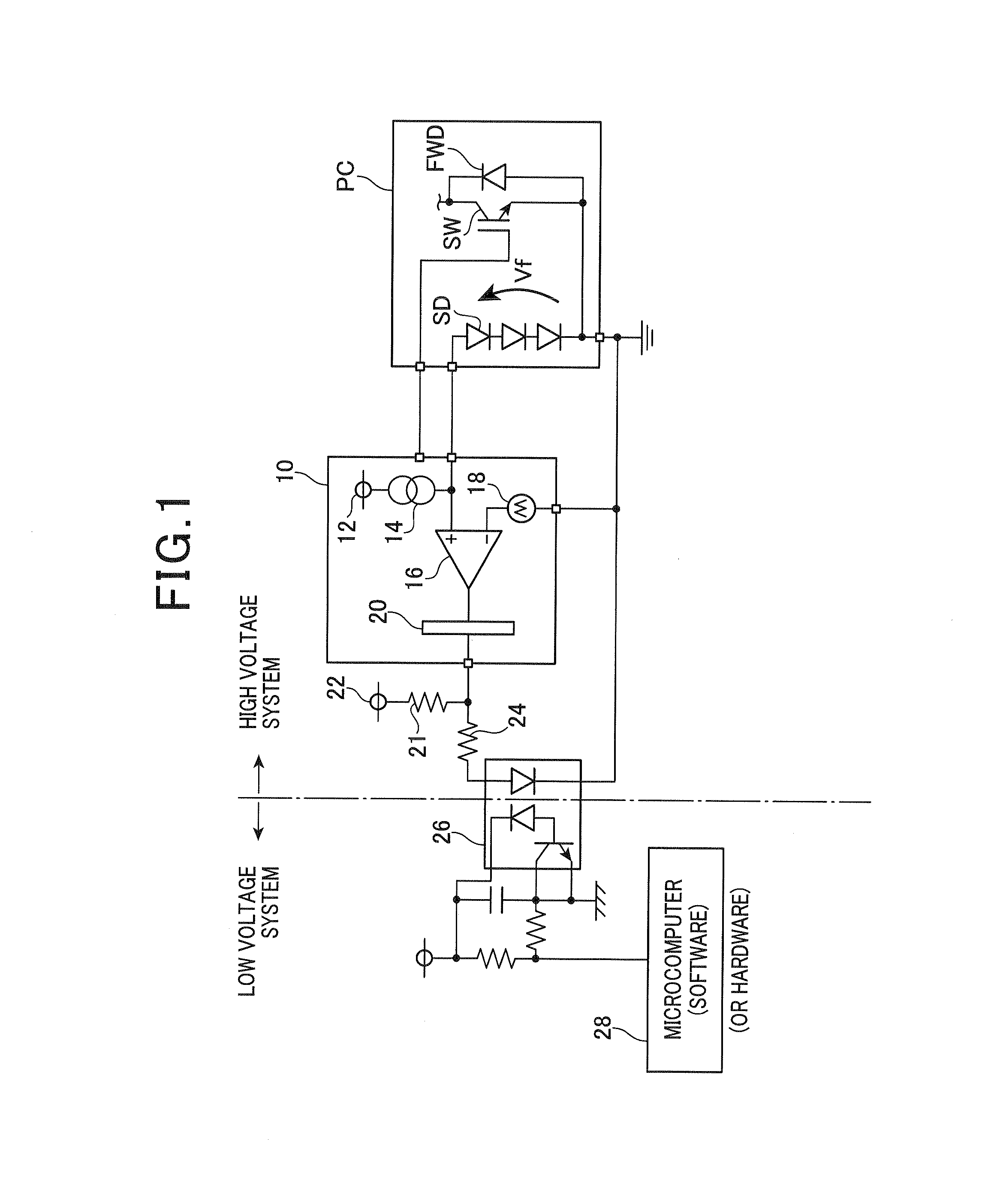
[0027]FIG. 1 is a view showing a structure of a system equipped with the error correction device according to the first exemplary embodiment.

[0028]The system equipped with the error correction device shown in FIG. 1 is comprised of a high voltage system (as a first section) and a low voltage system (as a second section) mounted to a vehicle. The low voltage system has a reference voltage of the body of a vehicle. The high voltage system is electrically insulated from the low voltage system. A power card PC is a power module mounted to the high voltage system in the system of the vehicle. The power card PC is comprised of a power switching element SW, a freewheel diode FWD, a temperature sensing diode SD which are packaged togeth...

Example

Second Exemplary Embodiment

[0074]A description will be given of the error correction device according to a second exemplary embodiment with reference to FIG. 10 and FIG. 11.

[0075]FIG. 10 is a view showing a structure of a frame used by the error correction device according to the second exemplary embodiment, in which corrected pulse signal values are stored. The difference between the second exemplary embodiment and the first exemplary embodiment will be explained for brevity.

[0076]The error correction device according to the second exemplary embodiment executes a process of setting the first correction pulse signal PulseX and the second correction pulse signal PulseY to the frame, which is different from the process processed by the error correction device according to the first exemplary embodiment. As shown in FIG. 10, data items of the first correction pulse signal PulseX and the second correction pulse signal PulseY are set into sections in adjacent frames which are adjacent in...

Example

Third Exemplary Embodiment

[0084]A description will be given of the error correction device according to a third exemplary embodiment with reference to FIG. 12 and FIG. 13.

[0085]FIG. 12 is a view showing a structure of a frame used by the error correction device according to the third exemplary embodiment, in which corrected pulse signal values are stored. The difference between the third exemplary embodiment and the second exemplary embodiment will be explained for brevity.

[0086]The microcomputer 28 as the error correction device according to the third exemplary embodiment executes a calculation process of calculating the time ratio of the pulse signal to a frame length and a setting process of setting the calculated time ratio of the pulse signal to a frame, which are different from the calculation process of calculating the time ratio of the pulse signal, and the setting process of setting or arranging data items including the calculated time ratio of the pulse signal into a frame...


PUM


Abstract

In an error correction device, a frame generation section receives pulse signals as temperature information of a power switching element transmitted from a PWM comparator. The frame generation section sets a first correction pulse signal, a second correction pulse signal and the temperature information sequentially into each frame. A pulse width of the first correction pulse signal corresponds to a pulse width when a time ratio thereof becomes 100%. A pulse width of the second correction pulse signal corresponds to a pulse width when a time ratio thereof becomes 50%. A microcomputer receives the temperature information through a photocoupler and corrects the received temperature information. The microcomputer calculates a temperature detection value of the power switching element on the basis of the corrected temperature information.

Description

CROSS-REFERENCE TO RELATED APPLICATION[0001]This application is related to and claims priority from Japanese Patent Application No. 2012-157718 filed on Jul. 13, 2012, the contents of which are hereby incorporated by reference.BACKGROUND OF THE INVENTION[0002]1. Field of the Invention[0003]The present invention relates to error correction devices to be used in physical property value detection devices comprised of a detection element, a modulation section and a detection section. The detection element detects a value of a physical property of a detection target, and outputs detection signals relating to the detected value of a physical property of the detection target. The modulation section modulates the detection signals outputted from the detection element into pulse signals, and outputs the pulse signals. The detection section receives the pulse signals transmitted from the modulation section through a pulse signal transmission path, and detects the value of the physical propert...

Claims


Application Information

Patent Timeline
IPC IPC(8): H04L1/20
CPCH04L1/206G06F11/24H03M1/504
Inventor HAMANAKA, YOSHIYUKI
Owner DENSO CORP
Why Eureka
Try Eureka