
Method for reducing nitrogen oxide levels in diesel engine exhaust gases

a technology of nitrogen oxide and diesel engine, which is applied in the direction of machines/engines, mechanical equipment, separation processes, etc., can solve the problems of difficult adaptation of pre-control models, difficult pre-control, and ammonia breakthroughs, and achieve the effect of reducing the nitrogen oxide level

Inactive Publication Date: 2014-01-23
DEUTZ AG
View PDF1 Cites 18 Cited by
  • Summary
  • Abstract
  • Description
  • Claims
  • Application Information

AI Technical Summary

Benefits of technology

The invention provides a way to reduce nitrogen oxides in diesel engine exhaust gases using selective catalytic reduction (SCR) with ammonia as the reducing agent. This method ensures the efficient use of SCR catalytic converters and prevents ammonia breakthroughs through the system. It also requires minimal calibration and data input.

Problems solved by technology

However, feeding an excess of reducing agent may result in ammonia breakthroughs through the SCR catalytic converter.
This pre-control is made difficult by the fact that, in particular, SCR catalytic converters, on the basis of zeoliths exchanged by transition metals, have a significant ammonia storage capacity.
This accumulator function of the catalytic converter makes optimum adaptation of the pre-control model difficult, since, due to the complexity of the chemical-physical processes in the SCR catalyst, they are very difficult to describe mathematically.
Model-supported regulation of the reducing agent feed therefore has the disadvantage that, in particular during the transient operation of the engine, maximum efficiencies of the SCR catalytic converter cannot be ensured at all operating points without ammonia breakthroughs.

Method used


Image

  • Method for reducing nitrogen oxide levels in diesel engine exhaust gases
  • Method for reducing nitrogen oxide levels in diesel engine exhaust gases
  • Method for reducing nitrogen oxide levels in diesel engine exhaust gases

Examples


Embodiment Construction

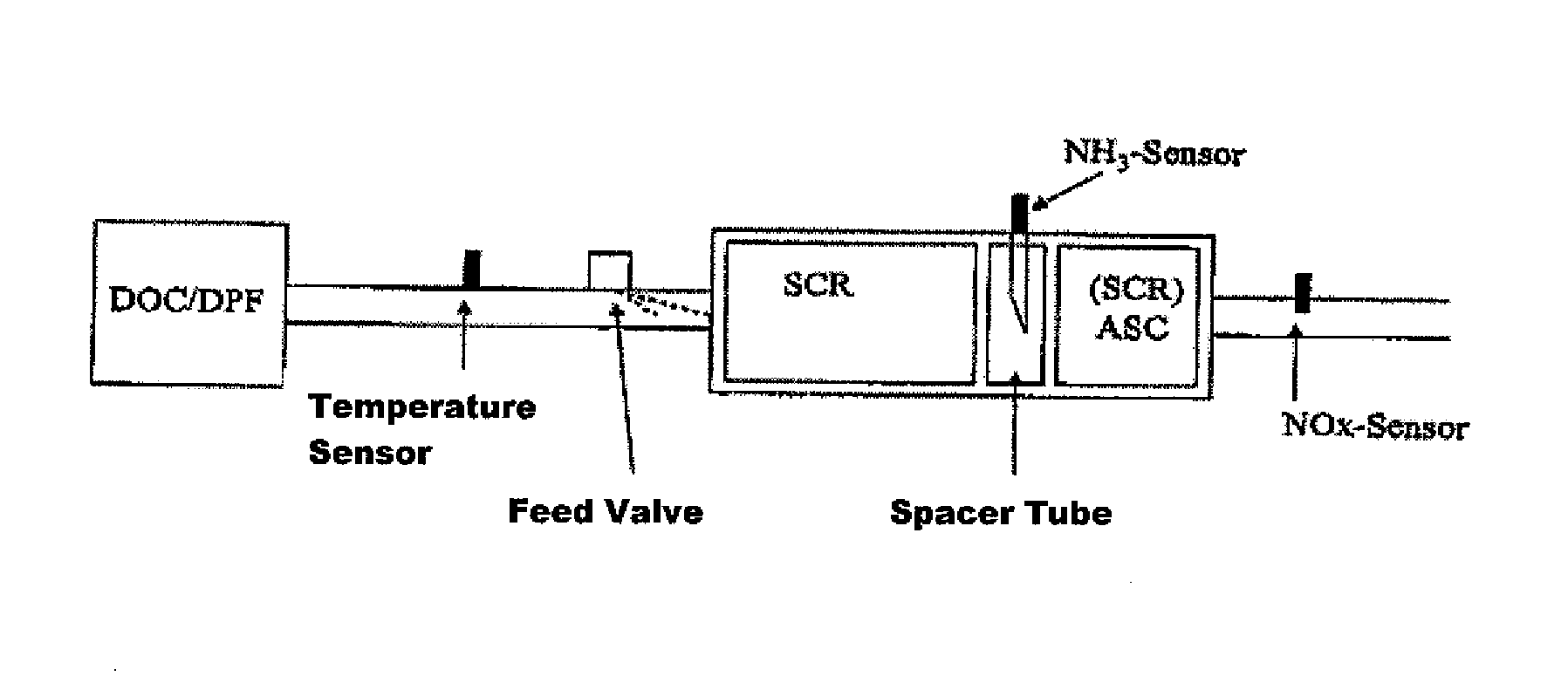
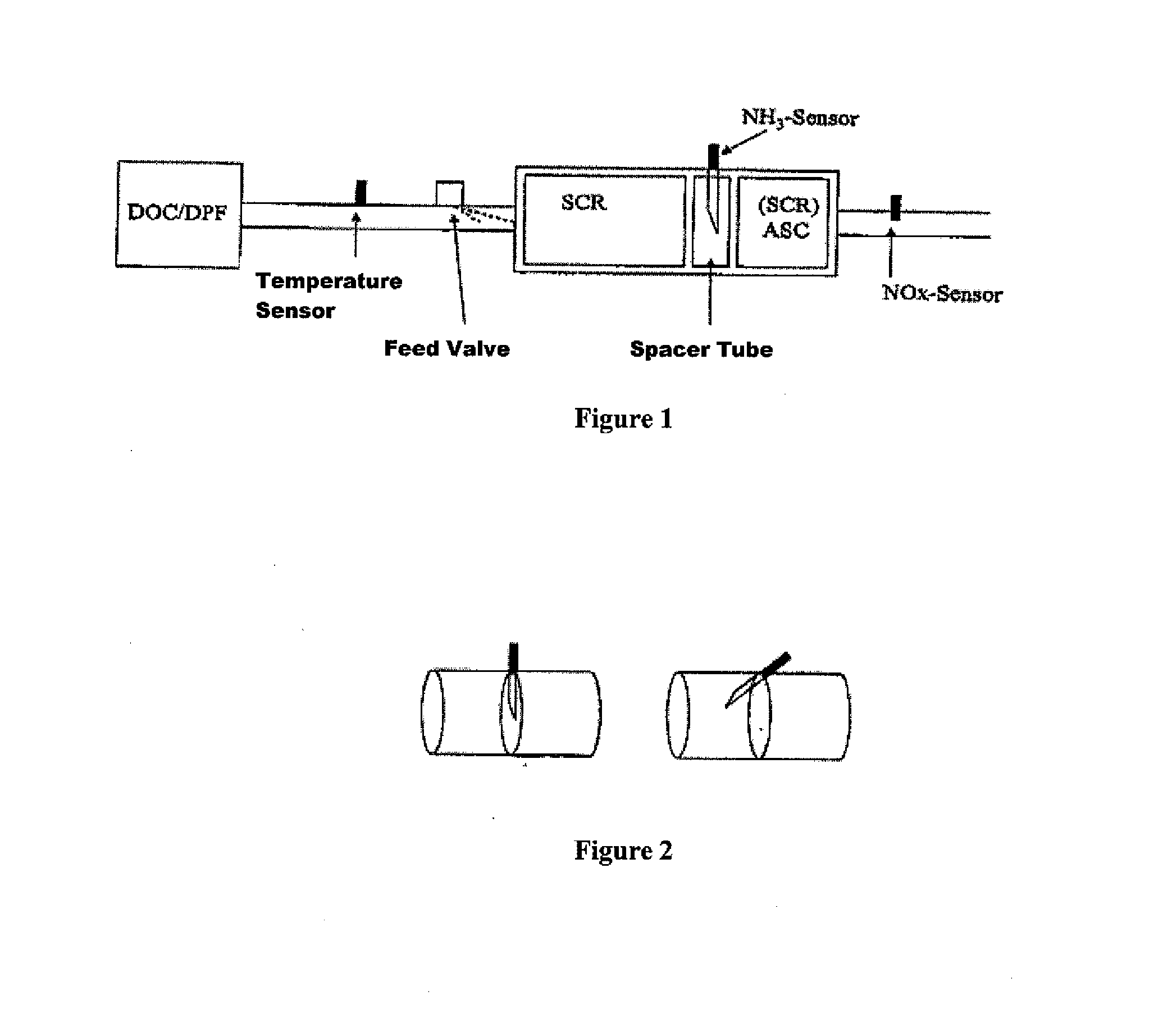
[0033]FIG. 1 schematically shows the construction of an exhaust gas treatment system for carrying out the method according to an embodiment of the present invention.

[0034]The exhaust gas generated by the engine and to be cleaned might first go, via an upstream DOC and / or DPF and a mixing pipe, to a first SCR unit, which reduces the nitrogen oxides contained in the exhaust gas to be cleaned using ammonia from the aqueous urea solution (AdBlue®), and which is formed by one or more SCR catalytic converters. The exhaust gas temperature is measured with the aid of a suitable temperature sensor in the mixing pipe between the DOC / DPF and the first SCR unit. The feeding device for urea solution, used to feed a predetermined quantity of urea solution into the exhaust gas to be cleaned, is situated downstream from the temperature sensor. On the mixing tube, which includes the feeding device and, if necessary, static mixers for better homogenization of the exhaust gas to be cleaned and the red...


PUM

PropertyMeasurementUnit
Temperatureaaaaaaaaaa
Concentrationaaaaaaaaaa

Abstract

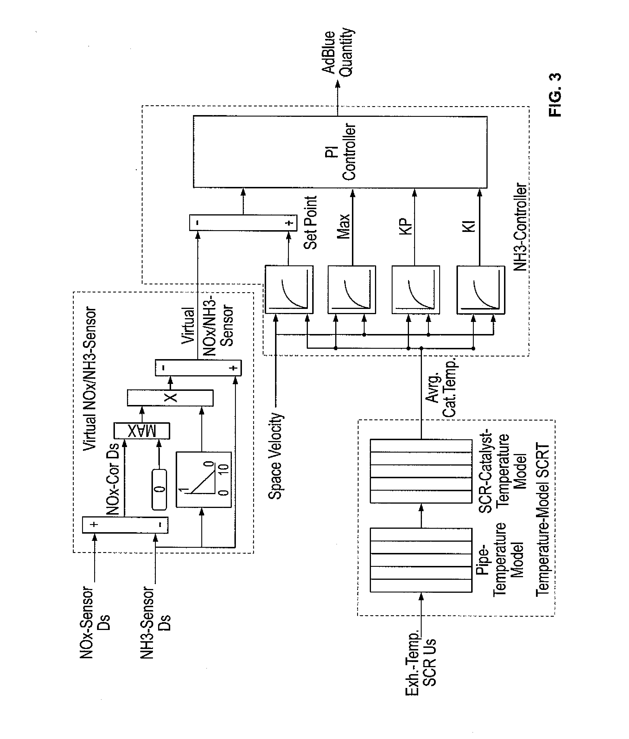
A method is described for reducing the nitrogen oxide levels in diesel engine exhaust gases with the aid of an exhaust gas treatment system, which includes a device for feeding ammonia and / or a compound decomposing to form ammonia, and two SCR units. An ammonia sensor is situated between the first and second SCR unit. A nitrogen oxide sensor is located in the exhaust pipe downstream from the second SCR unit. The signals of the ammonia sensor and the NOx sensor are combined in a defined manner to form the actual value of a virtual NOx / NH3 sensor, which is used as the input variable for a PI or PID controller, which regulates the quantity of reducing agent to be fed into the exhaust gas as needed.

Description

[0001]This claims the benefit of European Patent Application EP 12005203.0, filed Jul. 14, 2012 and hereby incorporated by reference herein.BACKGROUND[0002]To comply with the 2014 European and U.S. emission legislation (EU Stage IV and Tier 4 (final)) for non-road diesel engines, these diesel engines must be equipped with an exhaust gas cleaning system. Typical exhaust gas cleaning systems include, in addition to a diesel oxidation catalytic converter for oxidatively removing carbon monoxide and hydrocarbons, and, if necessary, a diesel particulate filter situated downstream therefrom, also a nitrogen removal unit. Units for selective catalytic reduction of nitrogen oxides with the aid of an SCR catalytic converter (SCR: Selective Catalytic Reduction), and a device for feeding ammonia or a compound decomposing to form ammonia in the exhaust gas stream to be cleaned, are typically used as the reducing agents for removing nitrogen oxides from diesel engine exhaust gases in utility and...

Claims


Application Information

Patent Timeline
IPC IPC(8): F01N3/10
CPCF01N3/10B01D53/9418B01D53/9477B01D53/9495F01N3/208B01D2251/2062B01D2257/406B01D2258/012F01N2560/021F01N2610/02F01N2560/026F01N2900/0418F01N13/0097F01N13/0093Y02A50/20Y02T10/12
Inventor WITTROCK, MEIKESWIATLAK, OLIVER
Owner DEUTZ AG
Learn More