Vegetable cutting apparatus

a technology for cutting equipment and vegetables, applied in the direction of sawing equipment, metal working equipment, manufacturing tools, etc., can solve the problems of inefficiency, inability to make significant profits, and inability to accurately cut vegetables manually in response to such demands, so as to achieve uniform cut products, reduce the effect of manual cutting, and reduce the number of cuts

Inactive Publication Date: 2014-01-23
MATSUMOTO HIDEO
View PDF0 Cites 4 Cited by
  • Summary
  • Abstract
  • Description
  • Claims
  • Application Information

AI Technical Summary

Benefits of technology

[0016]The present invention is as described above, offering advantages that the vegetables which have been supplied to the cutting unit are automatically fed at a constant pressure, being sandwiched between the conveyor belt, which is intermittently moved in a circulatory manner, and the holding roller, which is intermittently rotated in synchronization with the conveyor belt, thereby the vegetable feed pressure applied to the blade being uniform, and thus the size of the cut products being uniform, and in addition, the intermittently operated conveyor belt and the holding roller stop their operations at the time of cutting operation by the round blade with no feed pressure being applied to the round blade at the time of cutting, whereby smooth cutting assuring a neat cut end can be performed.
[0017]F

Problems solved by technology

Not only in the foodstuff factories, bento factories, supermarkets, and restaurants, but also in recent years, in the eating-out chain restaurants, the cut articles of vegetables are being demanded in quantity, however, making an operation of cutting the vegetables manually in response to such demands is, of course, non-efficient, and thus will never make any significant profit.
However, many of the apparatuses which have been conventionally proposed use a scheme in which vegetables to be cut are forced into a guide in the shape of a cylinder by hand, and with them, there have presented a p

Method used


Image

  • Vegetable cutting apparatus
  • Vegetable cutting apparatus
  • Vegetable cutting apparatus

Examples


Embodiment Construction

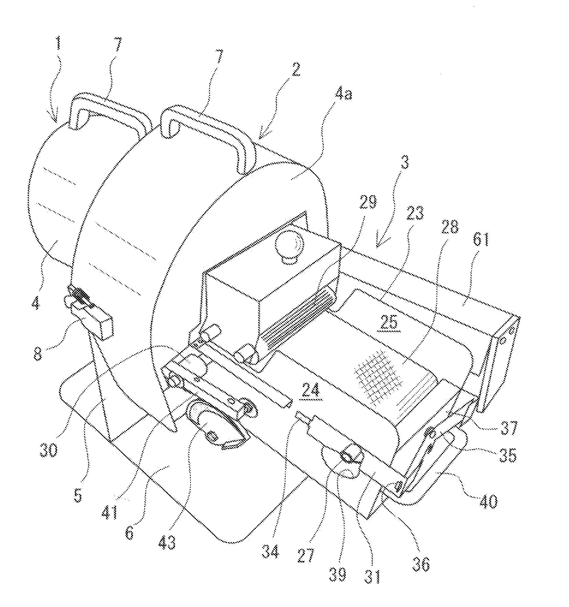
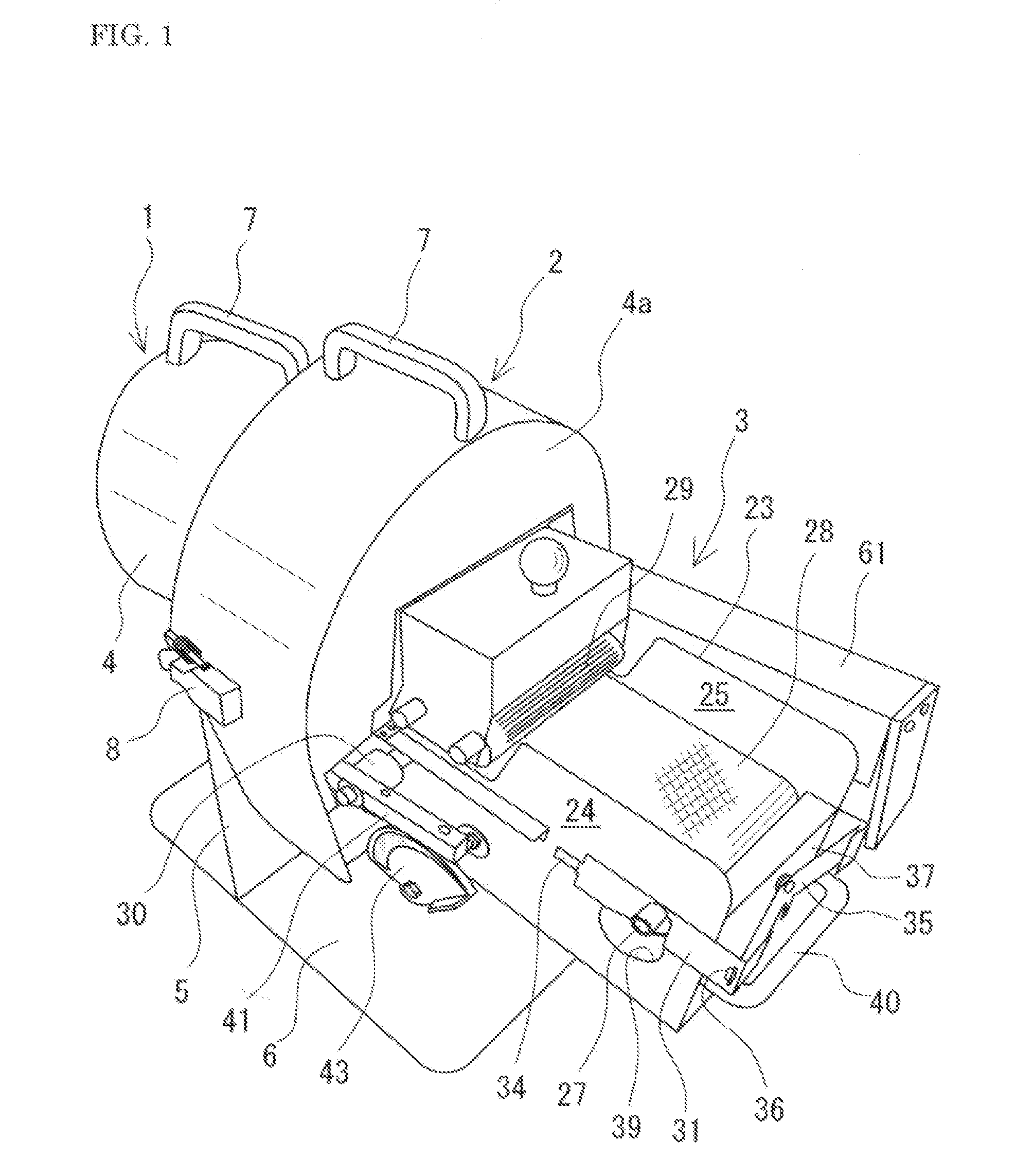
[0027]Hereinbelow, an embodiment of the present invention will be explained with reference to the accompanying drawings. FIG. 1 is a perspective view of one embodiment of an apparatus in accordance with the present invention, and the apparatus as shown in the figure includes a rotation driving unit 1 having a rotation driving means, a cutting unit 2 having a cutting means which is planetary gear-driven by the rotation driving means for cutting vegetables, and a feeding unit 3 having a feeding means for intermittently introducing the vegetables to be cut into the cutting unit 2.

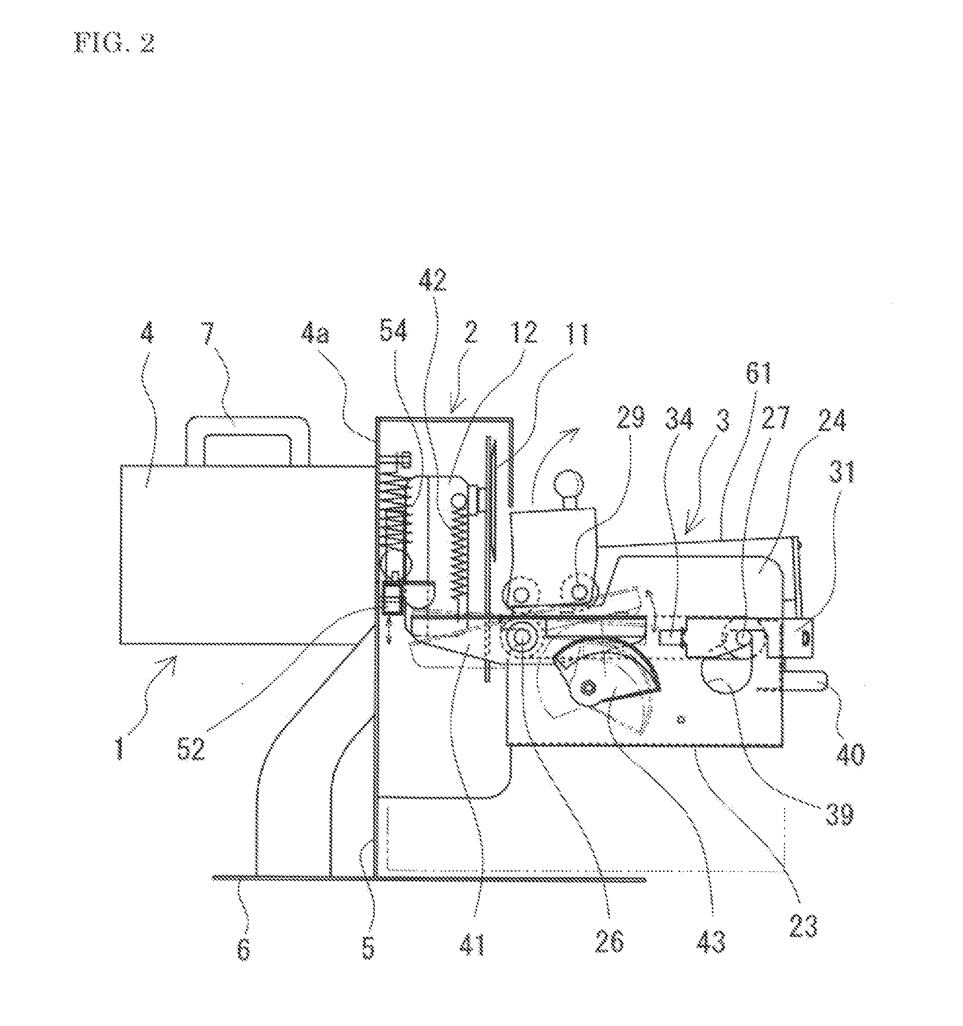
[0028]The rotation driving unit 1 and the cutting unit 2 are accommodated in a casing 4, 4a. The casing 4, 4a is divided into two by a vertical base plate 5, the one casing 4 housing the rotation driving unit 1, and the other casing 4a housing the cutting unit 2. The vertical base plate 5 is fixed to the casing 4, and the casing 4a is detachably attached to the vertical base plate 5 through a connection metal ...


PUM

PropertyMeasurementUnit
Timeaaaaaaaaaa
Shapeaaaaaaaaaa

Abstract

A vegetable cutting apparatus which includes a rotation driving unit, a cutting unit, and a feeding unit having a vegetable intermittent feeding device; the feeding unit is provided with a drive roller and a driven roller which are installed across side walls horizontally extending from the cutting unit, a conveyor belt which is installed between both rollers, and a holding roller which is disposed above the conveyor belt on the rear side thereof with a clearance to the conveyor belt being held; and a oneway clutch is mounted to the drive roller such that, with rocking turning thereof, the drive roller is intermittently rotation-driven, thereby the vegetables placed on the conveyor belt being intermittently fed, and at the time of cutting operation, feeding of the vegetables can be stopped.

Description

TECHNICAL FIELD[0001]The present invention relates to a vegetable cutting apparatus, and more particularly to a vegetable cutting apparatus for continuously cutting long green onions, onions, carrots, burdocks, and other vegetables, fruits, and mushrooms and other foodstuffs (hereinafter to be simply referred to as “vegetables”) to a desired size.BACKGROUND ART[0002]Not only in the foodstuff factories, bento factories, supermarkets, and restaurants, but also in recent years, in the eating-out chain restaurants, the cut articles of vegetables are being demanded in quantity, however, making an operation of cutting the vegetables manually in response to such demands is, of course, non-efficient, and thus will never make any significant profit. Then, in order to meet such demands, the present inventor has proposed various apparatuses which can efficiently perform a cutting operation on vegetables with a relatively simple mechanism, and has made them into products (Patent Literature 1: J...

Claims


Application Information

Patent Timeline
IPC IPC(8): B26D1/12
CPCB26D1/12B26D1/16B26D5/16B26D5/22B26D7/0625B26D2210/02Y10T83/6569
Inventor MATSUMOTO, HIDEO
Owner MATSUMOTO HIDEO
Why Eureka
Try Eureka