Interferometric Differential Gradiometer Apparatus and Method

a differential gradiometer and interferometer technology, applied in the field of differential gradi, can solve the problems of multiple separate measurements, inconvenient detection, and inability to locate and detect subsurface density anomalies, and achieve the effects of facilitating detection, enhancing signal-to-noise ratio, and facilitating detection

Inactive Publication Date: 2014-01-30
MICRO G LACOSTE
View PDF18 Cites 16 Cited by
  • Summary
  • Abstract
  • Description
  • Claims
  • Application Information

AI Technical Summary

Benefits of technology

[0020]This invention permits the direct measurement of the differential gradient of gravity, the gradient of the gradient of gravity, or the second spatial derivative of gravity, without the need to use gravimeters or gradiometers to make independent measurements at different times under different conditions, and then mathematically calculate the value of the differential gradient of gravity from the multiple separate measurements. The effects of background gravity and the background gravity gradient of the earth are inherently eliminated during the measurement, thereby greatly facilitating the detection of near field mass-variation sources such as high-density mineral or ore deposits or ore low-density underground voids or tunnels. The invention achieves a significantly enhanced signal-to-noise ratio when measuring the differential gradient of gravity caused by such near field sources, making the measurements easier to accomplish and more reliable.

Problems solved by technology

The large background of the earth's gravity requires that any direct gravity measurement to detect such subsurface anomalies have a very large dynamic range of parts per billion, otherwise direct gravity measurements will not be useful for locating and detecting such subsurface density anomalies.
Each of these multiple separate measurements involves some risk and amount of error.
Each gravimeter and gradiometer used in measuring gravity and the gradient of gravity is also subject to naturally-occurring and man-made vibrations and other physical perturbations.
These vibrations and perturbations cause minute changes in the path length of the reflected and reference light beams in a light beam interferometric instrument, causing interference fringes which are not related to the gravity characteristic measured.
Such anomalous interference fringes reduce the accuracy of the measurement and enhance the potential for errors.
Further still, each of the instruments is subject to unique vibrations and physical perturbations, which magnify the range of error when the measurements are subtracted from one another.
In theory, connected-together instruments are subject to the same physical influences, thereby introducing the same error into all the measurements.
When the measurements are subtracted, the common error in both signals is theoretically canceled or rejected.
However, the practical effect falls substantially short of complete common mode rejection.
It is practically impossible to achieve a sufficiently rigid connection between the two instruments to cause both to experience the same degree of perturbation.
It is impossible to freefall the test masses of the instruments at the same time, so each measurement is always subject to anomalies that do not influence the other measurement.
The different amounts of aerodynamic drag influence the freefall characteristics of each test mass differently, thereby introducing discrepancies.
Further still, the optics which conduct the light beams in the connected instruments are slightly different, and those differences introduce unique discrepancies.
Separate laser light sources for each instrument create unique phase changes in the light beams, which introduce anomalous fringe effects that may introduce measurement errors.
Inadvertent slight angular rotation or tilting of one or both the test masses during simultaneous freefall changes the length of the reflected light paths in that instrument, which again contributes to error when the two gravity or gravity gradient measurements are subtracted to determine the differential gradient of gravity.
These and other unique and adverse influences increase the possibility of deriving inaccurate measurements.
In addition, the mathematical manipulations of subtracting the measurements and dividing by the distance between the measurement locations may compound the errors.
The inability to achieve effective common mode rejection makes the measurement of the differential gradient of gravity using gravimeters and gradiometers error-prone, particularly in vibration-prone or perturbation-prone environments.

Method used


Image

  • Interferometric Differential Gradiometer Apparatus and Method
  • Interferometric Differential Gradiometer Apparatus and Method
  • Interferometric Differential Gradiometer Apparatus and Method

Examples


Embodiment Construction

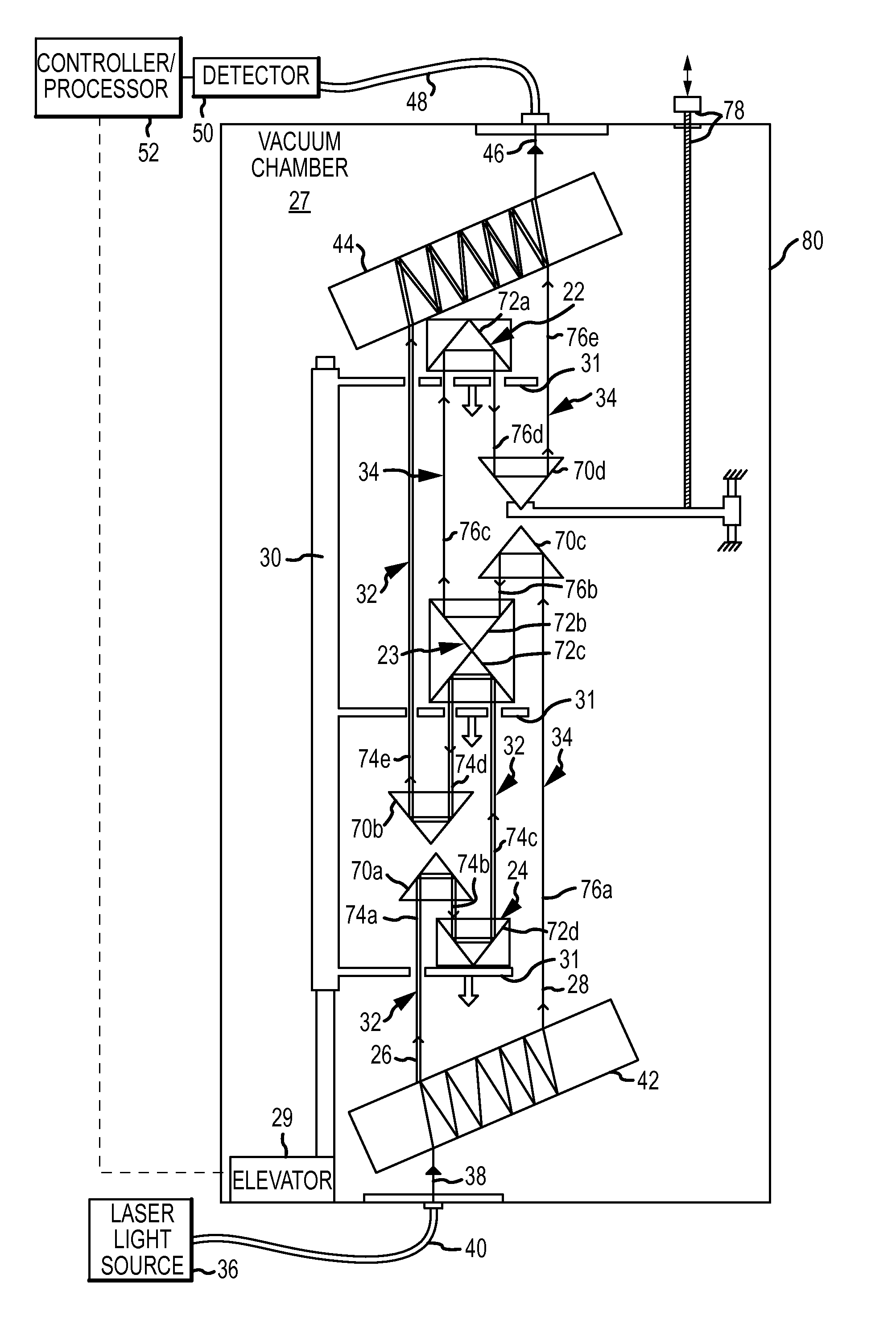
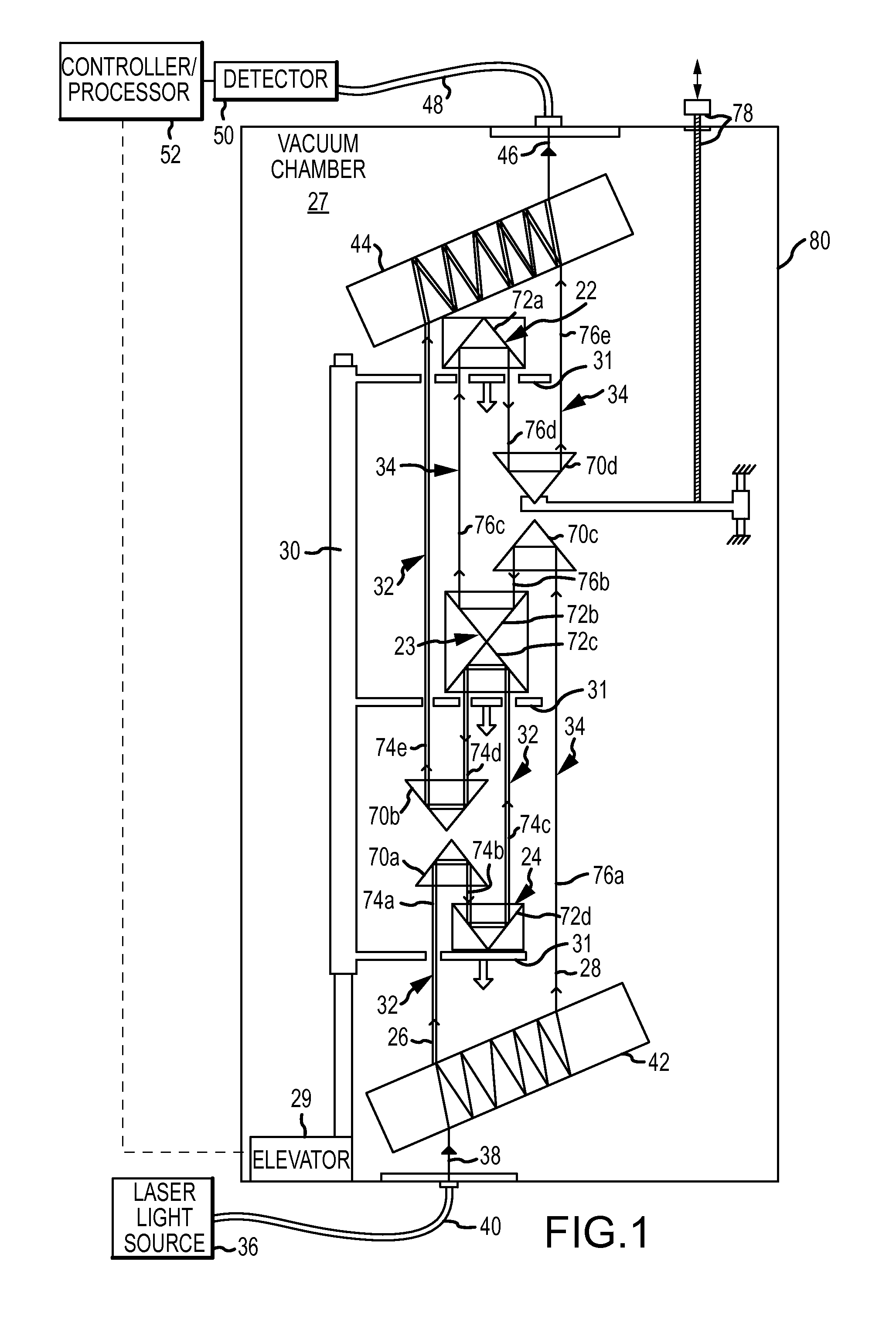
[0045]The present invention involves an optical interferometric differential gradiometer 20, shown in FIG. 1, but aspects of the invention may be embodied in other devices and methods for measuring a characteristic of gravity. The differential gradiometer 20 is used to measure a differential gradient of gravity represented by the relative differences in gravity gradients experienced by two pairs of test masses 22, 23 and 23, 24 which are released to fall freely and simultaneously only under the influence of gravity. The force of gravity acting on the lower test mass 24 is very slightly greater than the force of gravity acting on the middle test mass 23, since the lower test mass 24 is closer to the center of the earth's mass and therefore experiences a slightly greater gravitational force. Similarly, the force of gravity acting on the middle test mass 23 is very slightly greater than the force of gravity acting on the upper test mass 22, since the middle test mass 23 is closer to th...


PUM


Abstract

A differential gradient of gravity is directly measured from the interferometric combination of two light beams which reflect from pairs of three freefalling test masses. Optical path lengths of two beam arms change relative to one another because of differential gradient of gravity effects the test masses differently simultaneous freefall. The relatively large background of gravity and the gradient of gravity are eliminated from the measurement while simultaneously achieving a high level of common mode rejection of other spurious influences.

Description

CROSS REFERENCE TO RELATED INVENTIONS[0001]This invention is continuation in part of an invention described in U.S. patent application Ser. No. 13 / 558,138, titled “Interferometric Gradiometer Apparatus and Method,” filed Jul. 25, 2012. This invention is also a continuation in part of an invention described in U.S. patent application Ser. No. 13 / 564,548 titled “Test Mass and Method for Interferometric Gravity Characteristic Measurement,” filed Aug. 1, 2012. Both of these applications were filed by the inventors hereof, and both applications have been assigned to the assignee hereof. The subject matter of these U.S. patent applications is incorporated herein by this reference.FIELD OF THE INVENTION[0002]This invention relates to measuring a characteristic of gravity, and more specifically, to a new and improved differential gradiometer and method which directly measures a differential gradient of gravity, i.e. a gradient of a gradient of gravity or a second spacial derivative of gravi...

Claims


Application Information

Patent Timeline
Patent Type & Authority Applications(United States)
IPC IPC(8): G01V7/00
CPCG01V7/14
Inventor KLOPPING, FRED J.BILLSON, RYAN M.NIEBAUER, TIMOTHY M.
Owner MICRO G LACOSTE
Why Eureka
Try Eureka