Carburetor system for a carburetor engine

a carburetor engine and carburetor technology, which is applied in the direction of machine/engine, charge feed system, non-fuel substance addition to fuel, etc., can solve the problems of blockage of small fuel bores, sticking and clogging between moving parts, and gasoline component of two-stroke fuel vaporization

Active Publication Date: 2014-01-30
HUSQVARNA AB
View PDF8 Cites 17 Cited by
  • Summary
  • Abstract
  • Description
  • Claims
  • Application Information

AI Technical Summary

Benefits of technology

[0013]A first object of the present invention is to provide a fuel supply system, which reduces the risk of having moveable parts such as a valve member stuck in one position, and that provides good supply of fuel to an engine using the fuel supply system.

Problems solved by technology

However, after having stored the apparatus after even a very short use, the gasoline component of the two-stroke fuel evaporates and the two-stroke oil component of the fuel is left.
This oil can cause sticking and clogging between movable parts, and it may even block small fuel bores.
However, the oil is easily dissolved when it comes in contact with fresh fuel.
If the fuel valve is stuck in this state due to the evaporation of the fuel as described above, it may be difficult or even impossible to start the engine by pulling the cord, since the closed fuel valve blocks any fuel delivery to the main air passage.
Even if the fuel valve is partly open the user of the apparatus may have to pull the start cord of the engine repeatedly for a long time until fresh fuel has dissolved the oil residue and the fuel can continue to flow.
Actually, a user may even experience problems when trying to start a brand new product for the first time.
In a diaphragm carburetor having a fuel valve provided downstream of the fuel metering chamber, a connection of the systems to the fuel metering chamber will not accomplish an efficient air purging.

Method used


Image

  • Carburetor system for a carburetor engine
  • Carburetor system for a carburetor engine
  • Carburetor system for a carburetor engine

Examples


second embodiment

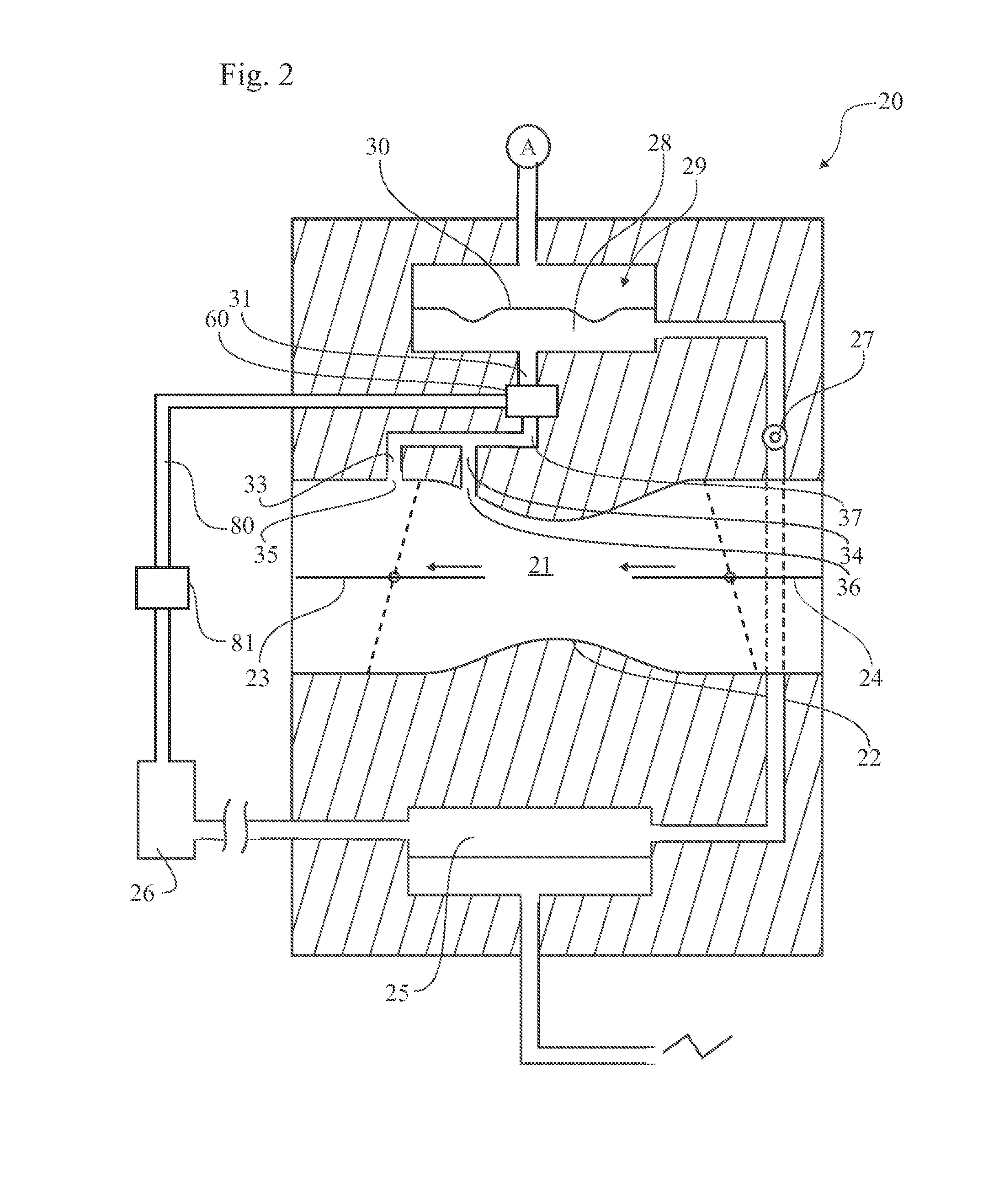
[0043]In a first and second embodiment shown inFIGS. 5, 6 the pump 81 operates as a purge pump 81a that vents trapped air from the system while wetting the fuel valve 60 with fuel.

fifth embodiment

[0044]And in a third, fourth and fifth embodiment shown in FIGS. 7, 8, 9 the pump 81 operates in the opposite direction, i.e. as a primer pump 81b, supplying fuel to the fuel valve 60.

[0045]To provide the desired direction of fuel flow through the purge pump 81a and the primer pump 81b, both of them preferably have two check valves incorporated in the pump design, one 82 upstream and the other 83 downstream of an elastic bulb. However, if desired, both of the check valves 82 and 83 may be provided as separate components. The check valves are not limited to a particular kind of check valve, but could be of many different kinds including ball check valves, duckbill valves etc. Specifically, the check valve may include a weighted body of any suitable form coupled to a resilient member, such as a compression or expansion spring.

[0046]The fuel valve 60 is preferably controlled by an electronic control unit, not shown, but described in WO 2009 / 116902 A1. The control unit receives sensor i...

third embodiment

[0061]FIG. 7 shows a third embodiment basically similar to the one in FIG. 5, but has a manually operated primer pump 81b, preferably by turning the direction of check valves. i.e. by connecting the downstream check valve 82 towards the fuel tank 26 and the upstream check valve 83 towards the fuel valve 60′. The fuel valve 60′ is preferably of the kind disclosed in FIG. 11, which is similar to the fuel valve designated 60, but differs in that the pump port 75 has been moved from directly communicating with the fuel cavity and instead communicating with a passage of the outlet port 71 provided downstream of the front valve seat 64. By directing the pump port 75 towards the opening at the front valve seat 64 and provided that the fuel pressure applied by the priming operation is large enough, fuel can flow through the valve irrespective of whether it is normally open or closed. Thereby, fresh fuel flows past and dissolves the possible oil residue that causes sticking and clogging betw...


PUM


Abstract

A fuel supply system for small two-stroke internal combustion engines for e.g. chain saws, line trimmers and similar hand-held power-tools including a diaphragm carburetor (20) equipped with a purging system (80a, 81a) or priming system (80b, 81b) for facilitating starting of the engine (1). Downstream of the diaphragm (30), the carburetor has a fuel valve (60) with a fuel cavity (73), which when the valve is not closed being connected via a fuel conduit (37) to a fuel nozzle (35, 36) in a main air passage (21) in the carburetor. The purging system or priming system including a fuel line (80a; 80b), which is provided with a manually operated pump (81a; 81b) and is connected between a fuel tank (26) and either the fuel cavity (73) or the fuel conduit (37).

Description

TECHNICAL FIELD[0001]The present invention relates to a fuel supply system of an internal combustion engine including a carburetor with a main air passage, the carburetor having a fuel pump supplying fuel to a fuel regulator from a fuel tank, said fuel supply system further including a fuel valve for controlling delivery of fuel to a main air passage of a carburetor of an internal combustion engine, the fuel valve including at least one inlet port for receiving fuel from a fuel regulator of the carburetor, at least one fuel outlet port for connecting to at least one nozzle in the air passage leading into the engine, a fuel cavity between the inlet port and the outlet port, and a valve member movable in a manner so as to enable at least two states, a first state permitting flow of fuel from the inlet port through the cavity to the outlet port of the valve, and a second state at least principally blocking such flow.[0002]It also relates to a hand held tool powered by a two stroke cran...

Claims


Application Information

Patent Timeline
Patent Type & Authority Applications(United States)
IPC IPC(8): F02M1/16
CPCF02M1/16F02B63/02F02M17/04
Inventor LINDSTROM, FREDRIKMARTINSSON, PAROTTOSSON, MAGNUSRYDBERG, RIKARD
Owner HUSQVARNA AB
Why Eureka
Try Eureka