Radiographic image capture device
a technology of radiographic image and capture device, which is applied in the direction of optical radiation measurement, instruments, x/gamma/cosmic radiation measurement, etc., can solve the problems of loss of radiographic image data output through analogue-to-digital converter, increase in deformation amount and vibration amplitude, etc., to achieve efficient suppression or prevention of deformation and vibration of flexible substrate, and increase heat dissipation capability
- Summary
- Abstract
- Description
- Claims
- Application Information
AI Technical Summary
Benefits of technology
Problems solved by technology
Method used
Image
Examples
first exemplary embodiment
[0069]Explanation follows regarding a portable radiographic image detector configuring a radiographic image capture device of a first exemplary embodiment of the present invention, which is an example of the present invention applied to what is referred to as an electronic cassette.
[0070][Overall Configuration of Radiographic Image Capture Device]
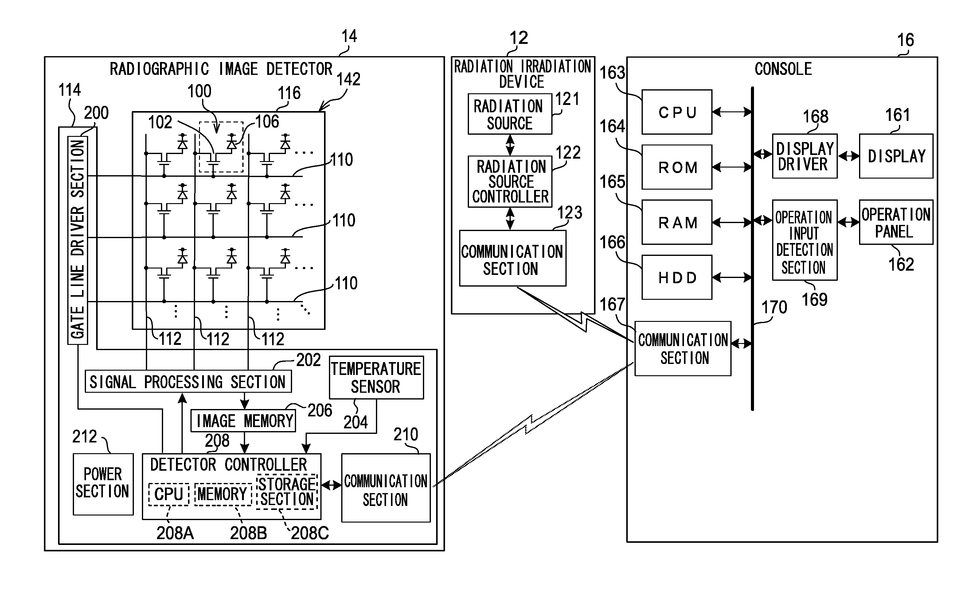
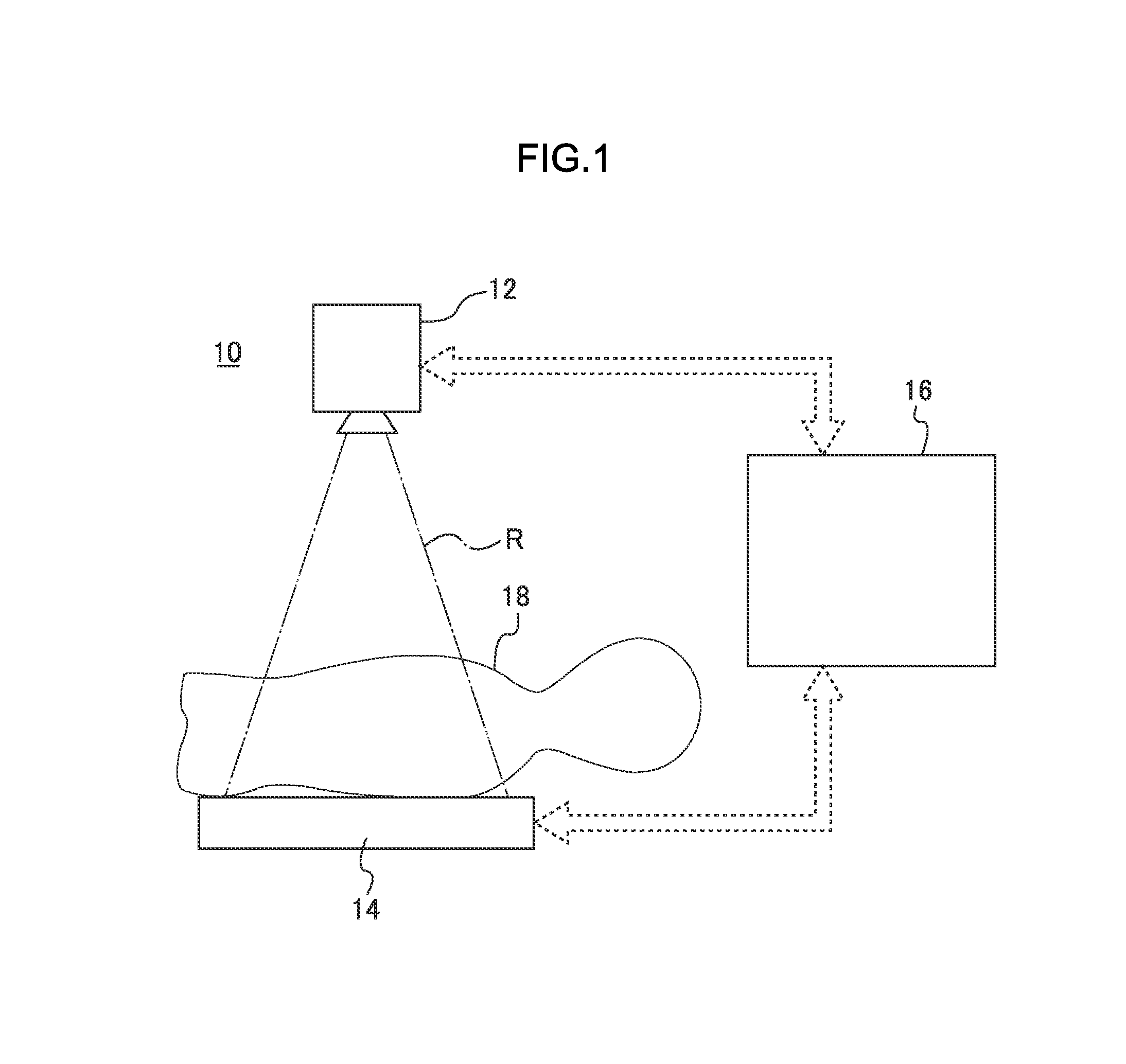
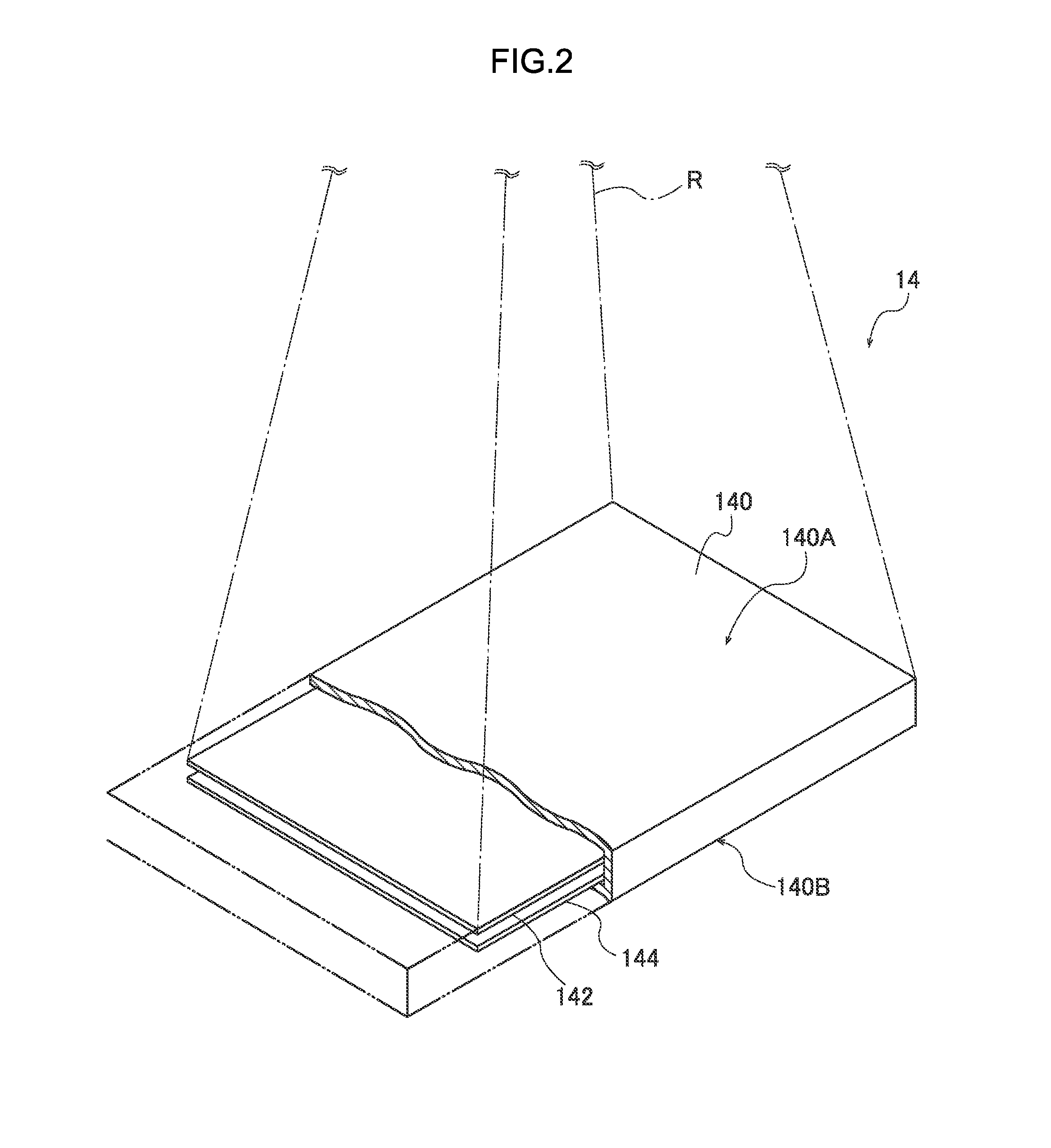
[0071]As illustrated in FIG. 1, a radiographic image capture device 10 according to a first exemplary embodiment is configured including a radiation irradiation device 12, a radiographic image detector 14 (electronic cassette) and a console 16. The radiation irradiation device 12 generates radiation R, and irradiates the radiation R onto an investigation subject 18 (for example a patient for imaging a radiographic image). The radiographic image detector 14 generates radiographic image data obtained by the radiation R that has passed through the investigation subject 18. The radiographic image detector 14 is a portable type that is capable o...
second exemplary embodiment
[0171]Explanation follows of a second exemplary embodiment of the present invention as an example of the radiographic image detector 14 of the radiographic image capture device 10 according to the first exemplary embodiment described above in which the plan view profile of the reinforcement member has been modified.
[0172][Radiographic Image Detector Equipment Structure]
[0173]As illustrated in FIGS. 9A and 9B, in the radiographic image detector 14 according to the second exemplary embodiment, reinforcement members 186B are provided at the flexible substrates 182. As well as on a low wiring density region 184B, the reinforcement members 186B are also provided at a high wiring density region 184A, on a signal processing section 202 (first electronic component), on second electronic components 242A to 242D and on third electronic components 242E, 242F. The reinforcement members 186B are moreover disposed contiguously over these regions and components.
[0174]Specific materials and manufac...
third exemplary embodiment
[0179]Explanation follows regarding a third exemplary embodiment of the present invention as an example in which the radiographic image detector 14 of the radiographic image capture device 10 according to the first exemplary embodiment is provided with fixing members 187A in addition to the reinforcement member 186A.
[0180][Equipment Structure of Radiographic Image Detector]
[0181]As illustrated in FIG. 10A and FIG. 10B, in the radiographic image detector 14 according to the third exemplary embodiment, the reinforcement member 186A is provided at least at the low wiring density region 184B of the flexible substrate 182, and the fixing members 187A are also provided at the regions where the signal processing sections 202 (first electronic components) are provided. The fixing members 187A are interposed in this case between the back face of the regions of the flexible substrate 182 where the signal processing sections 202 are mounted and the support member 180, and the low wiring densit...
PUM
 Abstract
Description
Claims
Application Information
 - R&D
- Intellectual Property
- Life Sciences
- Materials
- Tech Scout
- Unparalleled Data Quality
- Higher Quality Content
- 60% Fewer Hallucinations
Browse by: Latest US Patents, China's latest patents, Technical Efficacy Thesaurus, Application Domain, Technology Topic, Popular Technical Reports.
© 2025 PatSnap. All rights reserved.Legal|Privacy policy|Modern Slavery Act Transparency Statement|Sitemap|About US| Contact US: help@patsnap.com


