Eureka AIR delivers breakthrough ideas for toughest innovation challenges, trusted by R&D personnel around the world.

High voltage field balance metal oxide field effect transistor (FBM)

Active Publication Date: 2014-01-30
ALPHA & OMEGA SEMICON INC
View PDF2 Cites 30 Cited by
  • Summary
  • Abstract
  • Description
  • Claims
  • Application Information

AI Technical Summary

Benefits of technology

The present invention provides a new and improved device configuration and manufacturing method for a semiconductor power device that reduces RdsA (the on-state resistance) by forming a highly doped epitaxial layer near the top surface of a semiconductor substrate and then forming trenches lined with oxides and filled with conductive material, within the highly doped epitaxial layer. The conductive material within the trenches are connected to a source electrode with buried P-regions formed underneath each source trench to function as charge compensating layers for the highly doped drift region to enable it to sustain high voltage while maintaining low series resistance.

Problems solved by technology

Conventional technologies to configure and manufacture high voltage semiconductor power devices are still confronted with difficulties and limitations to further improve the performances due to different tradeoffs.
However, a heavily doped epitaxial layer also reduces the breakdown voltage sustainable by the semiconductor power device.
However, this structure shifts the burden of supporting nearly all of the voltage to the oxide layer that lines the trench.
Increasing the thickness of the oxide in order to support more voltage also increases the stress in the device.
Therefore, the BV is limited to lower voltage devices such as those rated below 200V.
However, this too suffers from the same limitations as the Sapp device.
The absence of an electrode within the trenches places a stringent burden on accurate charge balance to achieve high breakdown.
However, the presence of a large gate electrode significantly increases the gate to drain capacitance of this structure, resulting in higher switching losses.
In addition, the Baliga device presents the additional manufacturing complexity of having a linearly graded doping profile in the drift region.
However, the manufacturing of this structure requires complex fabrication processes that include deep trenches, thick liner oxide, and a doping concentration gradient.
However, superjunction devices require complex processing and many additional masking steps, and therefore are expensive to produce.

Method used


Image

  • High voltage field balance metal oxide field effect transistor (FBM)
  • High voltage field balance metal oxide field effect transistor (FBM)
  • High voltage field balance metal oxide field effect transistor (FBM)

Examples


Embodiment Construction

[0030]Although the following detailed description contains many specific details for the purposes of illustration, anyone of ordinary skill in the art will appreciate that many variations and alterations to the following details are within the scope of the invention. Accordingly, the exemplary embodiments of the invention described below are set forth without any loss of generality to, and without imposing limitations upon, the claimed invention.

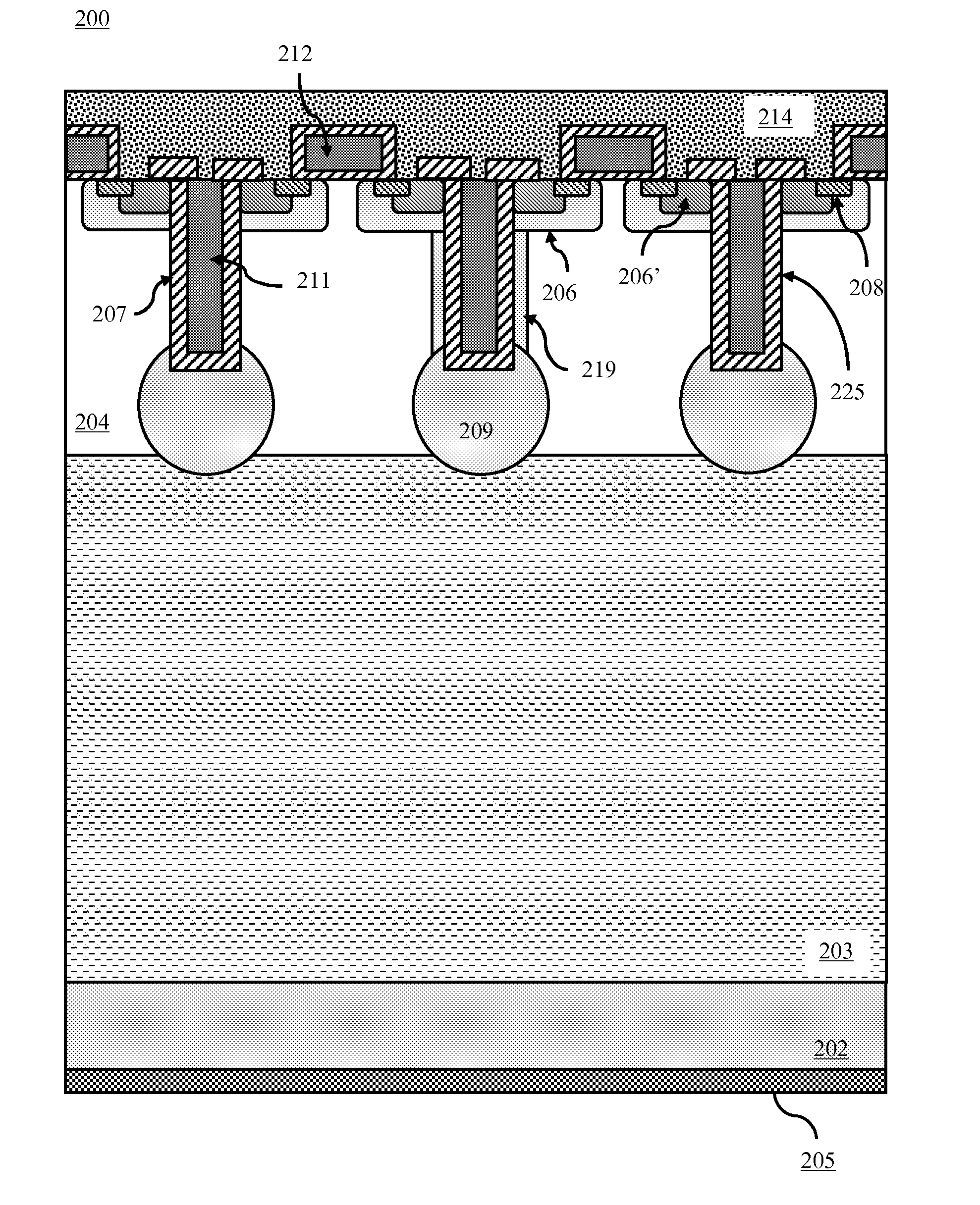
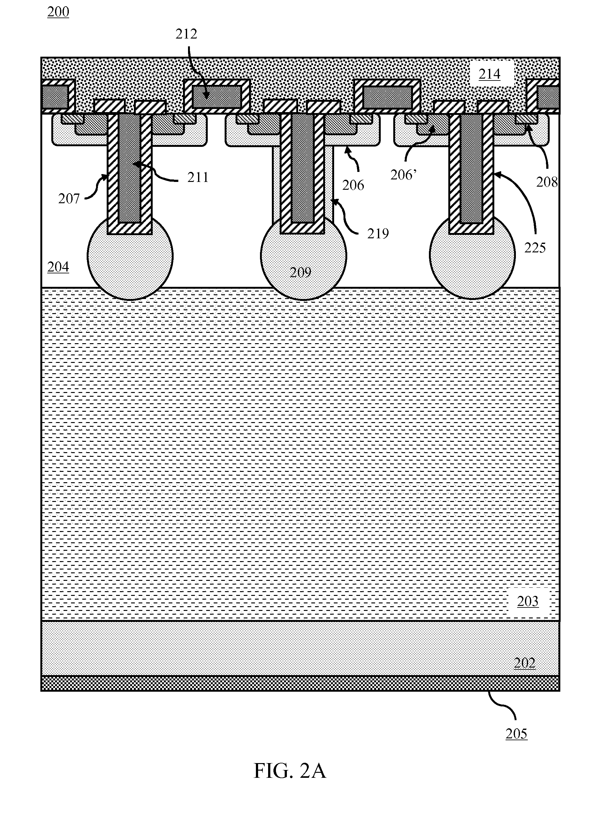
[0031]In the following Detailed Description, reference is made to the accompanying drawings, which form a part hereof, and in which is shown by way of illustration specific embodiments in which the invention may be practiced. In this regard, directional terminology, such as “top,”“bottom,”“front,”“back,”“leading,”“trailing,” etc., is used with reference to the orientation of the figure(s) being described. Because components of embodiments of the present invention can be positioned in a number of different orientations, the directional termin...


PUM


Abstract

A semiconductor power device formed in a semiconductor substrate comprising a highly doped region near a top surface of the semiconductor substrate on top of a lightly doped region supported by a heavily doped region. The semiconductor power device further comprises source trenches opened into the highly doped region filled with conductive trench filling material in electrical contact with the source region near the top surface. The semiconductor power device further comprises buried P-regions disposed below the source trenches and doped with dopants of opposite conductivity from the highly doped region. It is emphasized that this abstract is provided to comply with the rules requiring an abstract that will allow a searcher or other reader to quickly ascertain the subject matter of the technical disclosure. It is submitted with the understanding that it will not be used to interpret or limit the scope or meaning of the claims.

Description

CROSS-REFERENCE TO RELATED APPLICATION[0001]This application is related to commonly-assigned, co-pending application Ser. No. 13 / 199,381, filed Oct. 25, 2011, the entire disclosures of which are incorporated herein by reference.[0002]This application is related to commonly-assigned, co-pending application Ser. No. 13 / ______, entitled “TERMINATION DESIGN FOR HIGH VOLTAGE DEVICE” (Attorney Docket No. ANO-054 / US) to Lingpeng Guan et al filed the same day as the present application, the entire disclosures of which are incorporated herein by reference.[0003]This application is related to commonly-assigned, co-pending application Ser. No. 13 / ______, entitled “CORNER LAYOUT FOR HIGH VOLTAGE SEMICONDUCTOR DEVICE” to Lingpeng Guan et al. (Attorney Docket No. ANO-055 / US, filed the same day as the present application, the entire disclosures of which are incorporated herein by reference.FIELD OF THE INVENTION[0004]Embodiments of the present invention are related to semiconductor power devices. ...

Claims


Application Information

Patent Timeline
IPC IPC(8): H01L21/336H01L29/78
CPCH01L29/0611H01L29/401H01L29/66484H01L29/7831H01L21/26586H01L29/0623H01L29/0878H01L29/1095H01L29/66712H01L29/7802H01L29/7811H01L2924/0002H01L2924/00H01L29/0615H01L29/0634H01L29/0696H01L29/404H01L29/407H01L29/7813
Inventor BHALLA, ANUPYILMAZ, HAMZABOBDE, MADHURGUAN, LINGPENGHU, JUNKIM, JONGOHDING, YONGPING
Owner ALPHA & OMEGA SEMICON INC
Why Eureka
Eureka Blog
Learn More