
Laser projector with reduced speckle

a laser projector and speckle technology, applied in the field of projectors, can solve the problems of deteriorating image quality, long operating life, and high intensity light beam, and achieve the effects of reducing the cost of production, and improving the quality of production

Active Publication Date: 2014-01-30
BARCO NV
View PDF8 Cites 59 Cited by
  • Summary
  • Abstract
  • Description
  • Claims
  • Application Information

AI Technical Summary

Benefits of technology

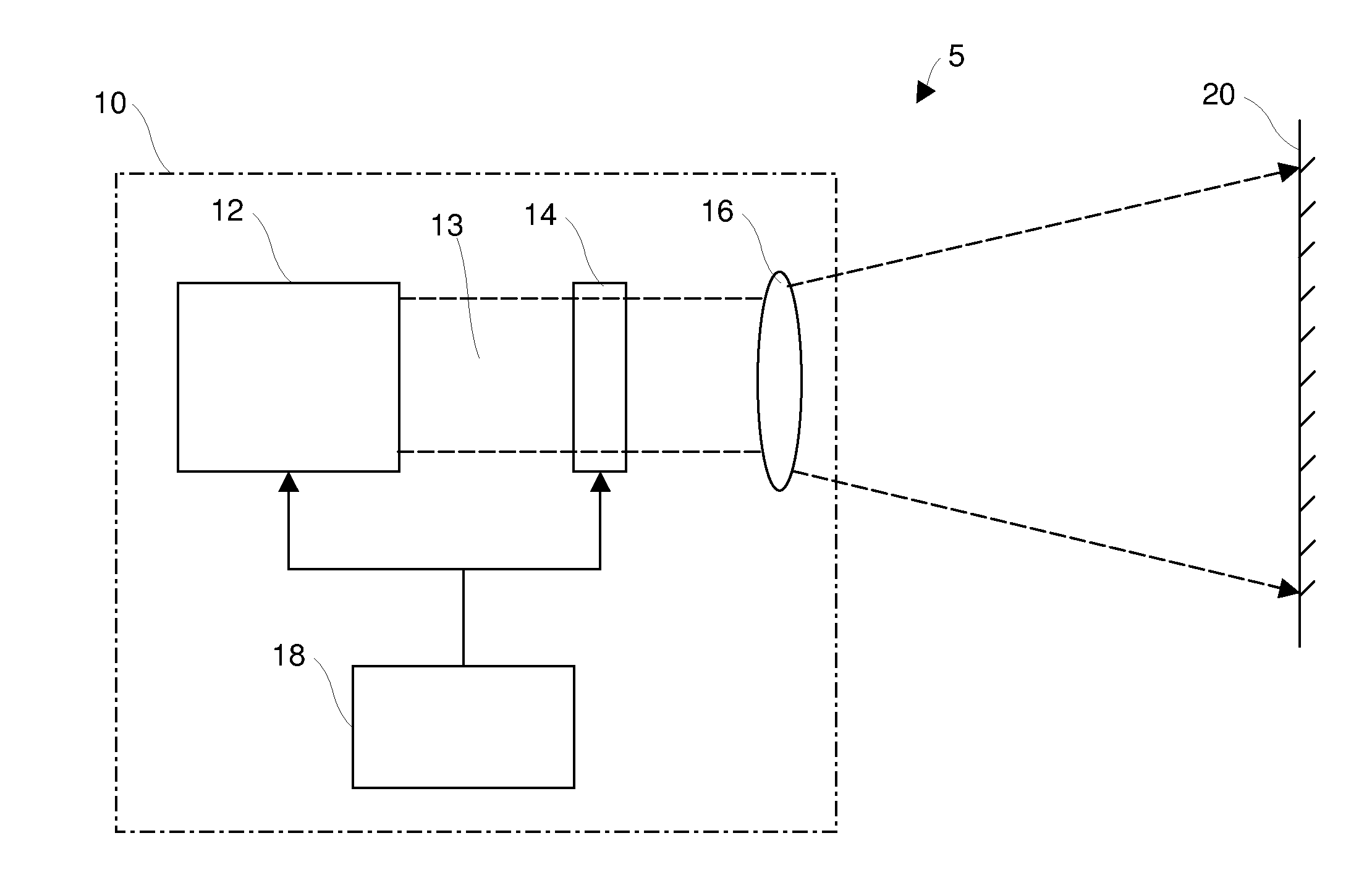
This patent is about a new light source for a projector system and a way to operate it. The invention aims to provide a more effective and reliable light source for this purpose.

Problems solved by technology

They emit a high intensity light beam and have a very long operating lifetime.
However, laser light sources also have some disadvantageous properties.
Speckle is typically seen as a granular structure on the screen which deteriorates the image quality and is distracting to a viewer.
A drawback of this approach is that different angles are generated sequentially by controlling the motion of the beam deflector.
This poses a serious eye-safety risk at high projector brightness as all the light at a certain moment in time appears to originate from a single spot in the projection lens aperture.
Furthermore, negative effects are likely to occur when used with certain types of light modulators that are driven by pulse width modulation (e.g. micro-mirror arrays).
The disadvantages of this approach are the long optical path length and the precise alignment required to fulfill the overlapping far field condition.
However for practical high-end projection systems this approach only cannot deliver the desired level of speckle reduction.
The size and acceptance angle limits of commercial light valves restrict the amount of angular diversity that can be introduced.

Method used


Image

  • Laser projector with reduced speckle
  • Laser projector with reduced speckle
  • Laser projector with reduced speckle

Examples


diversity embodiment

Wavelength and Angular Diversity Embodiment

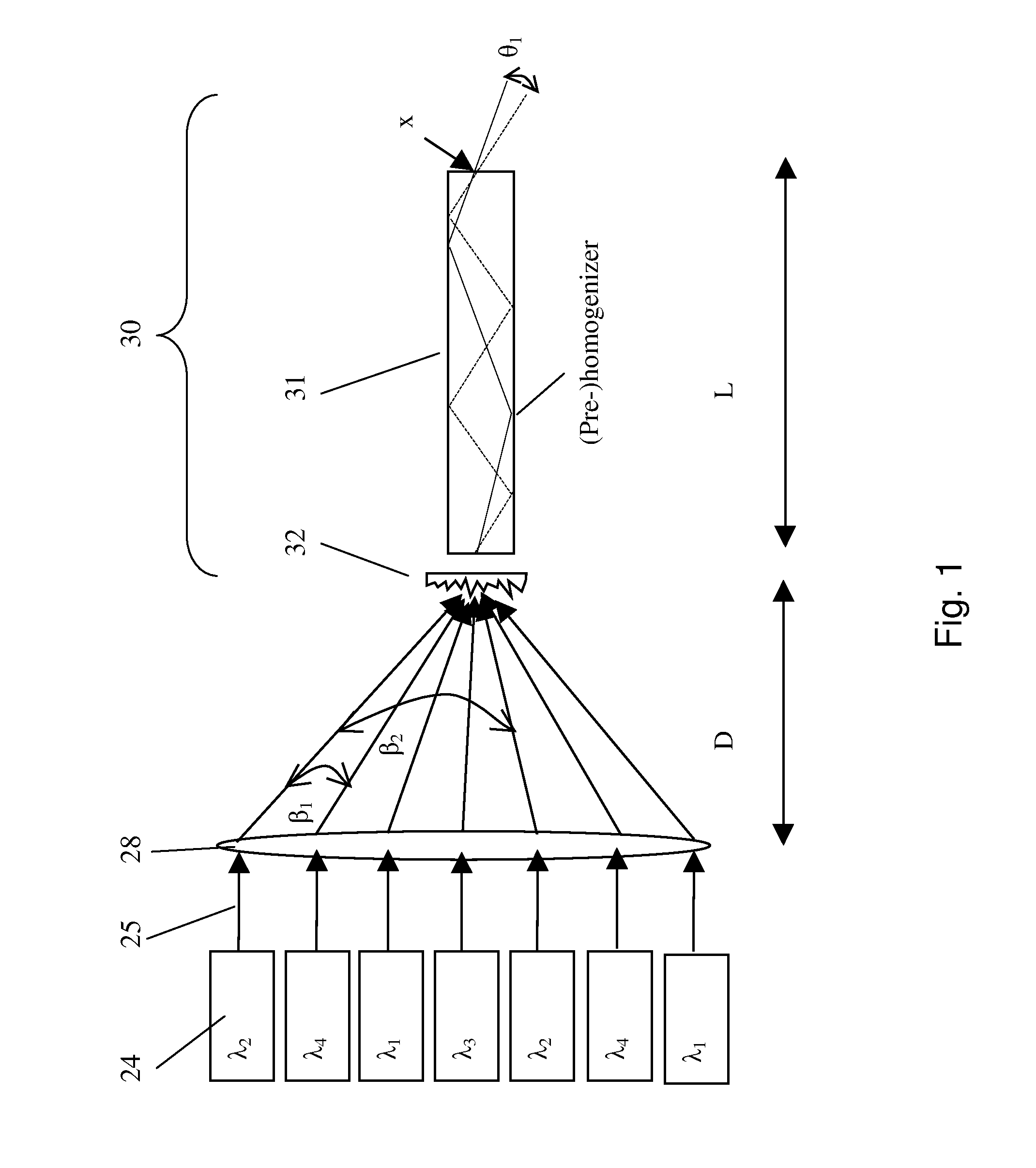
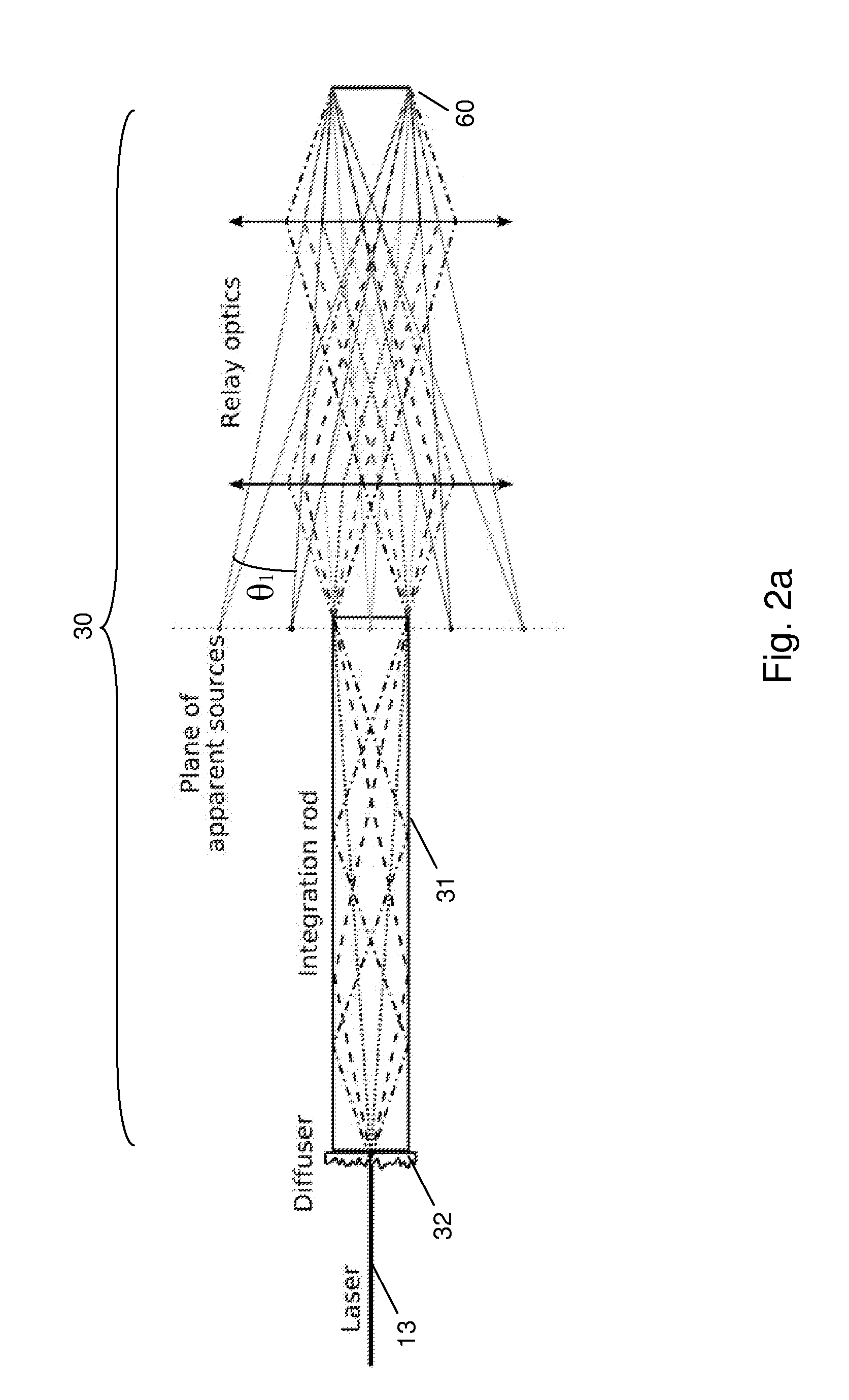
[0085]An embodiment of the present invention is shown in FIG. 10. FIG. 10 shows an integrator 30 which comprises two integrator elements 31, 33 and an intermediate or second diffuser or refractive element or lenslet array or refractive prism array 34. This will be called a “dual integrator”. The integrator 30 is adapted to fill the étendue of the projector as uniformly as possible, without scattering light over larger angles, which are not accepted by the projectors optical system and projection lens (leading to reduced light efficiency). The two integrator elements 31, 33 are arranged sequentially along a lightpath between the light sources 24 and light modulator 14. The two integrators are not shown as being in physical contact with each other with relay optics in between to image the exit of integrator 31 onto the entrance of integrator 33 and diffuser element 34. However, if there are a sufficiently high number of incoherent laser emitt...


PUM


Abstract

The present invention provides a light source for a projector system, and method of operating the light source as well as a projector system that provides:i. a substantially uniform brightness across the surface of an image modulator, andii. at each point of the surface of the image modulator a more uniform filling of the available angular space.Embodiments of the present invention use a laser light source for use with an image modulator, the light source emitting light with multiple wavelengths for at least one primary color and a light integrator system that for each of the wavelengths is adapted to provide:i. a substantially uniform brightness across the surface of the image modulator, andii. at each point of the surface of the image modulator a more uniform filling of the available angular space.

Description

FIELD OF THE INVENTION[0001]This invention relates to a projector which uses a laser light source, an integrating system for such a projector and methods to reduce speckle generated by such a projector as well as to a method of using such a projector, a controller for such a projector and a method of operating such a projector.BACKGROUND TO THE INVENTION[0002]Projection systems require a high quality light source. While projection systems have traditionally used discharge lamps as a light source, there is now interest in alternative light sources such as lasers. Lasers have several advantageous properties. They emit a high intensity light beam and have a very long operating lifetime. However, laser light sources also have some disadvantageous properties. A laser light source emits a narrow spectrum of coherent light and projection systems with laser light sources can suffer from an effect called “speckle”. Speckle is typically seen as a granular structure on the screen which deterio...

Claims


Application Information

Patent Timeline
IPC IPC(8): G02B27/48
CPCG02B27/48G02B27/0905G02B27/0994G03B21/2033G03B21/208G02B27/0927G02B27/0955H04N9/3152
Inventor JANSSENS, PETER
Owner BARCO NV
Learn More