
Mixed Fiber Structure used on a Bicycle

a technology of mixed fiber and bicycle, which is applied in the direction of cycle equipment, textiles and papermaking, thin material processing, etc., can solve the problems of high cost of carbon fiber fully made, so as to reduce the manufacturing cost of the present invention.

Inactive Publication Date: 2014-01-30
GIANT KUNSHAN
View PDF3 Cites 1 Cited by
  • Summary
  • Abstract
  • Description
  • Claims
  • Application Information

AI Technical Summary

Benefits of technology

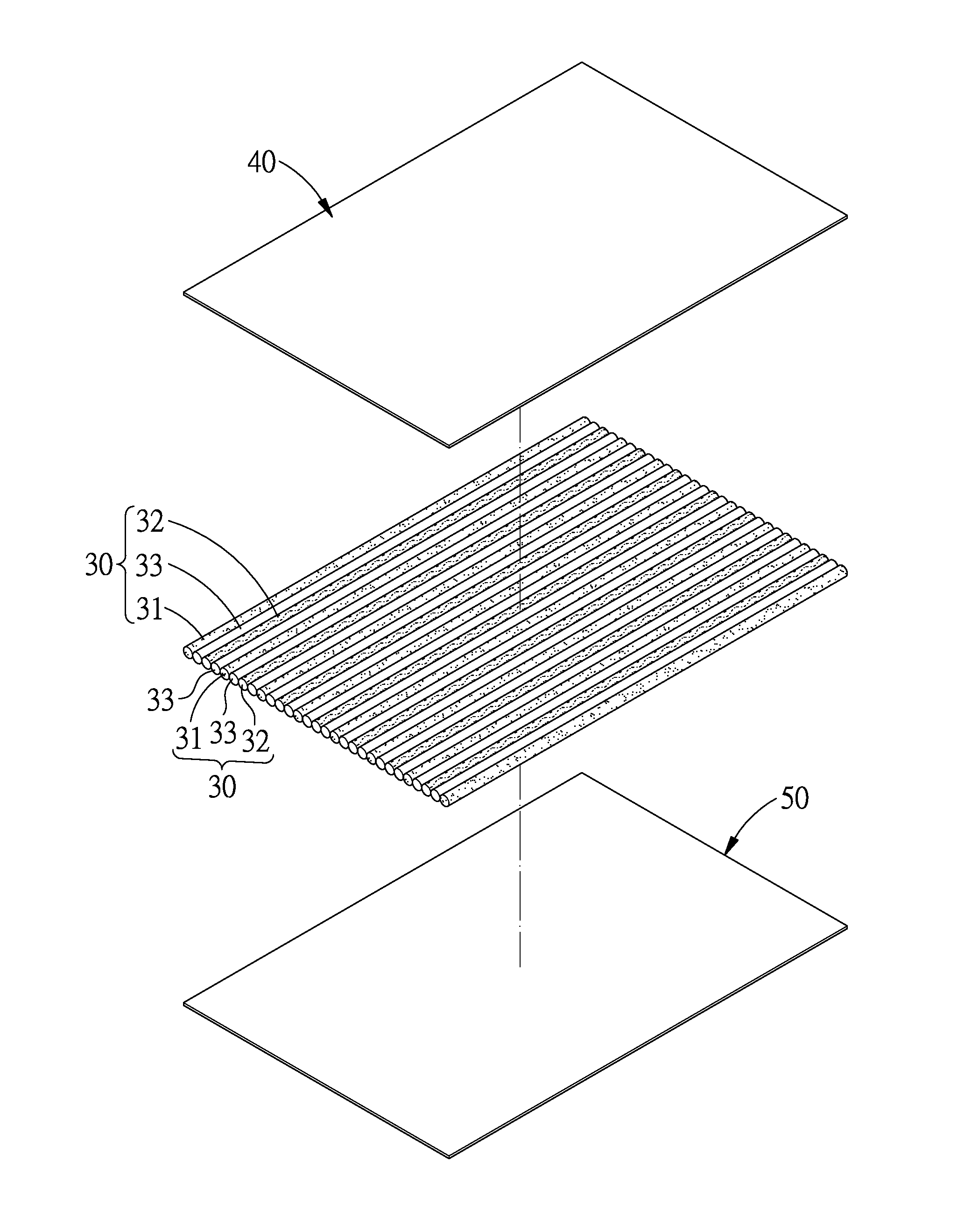
The present invention is a low-cost mixed fiber structure for bicycles that meets toughness and strength requirements without being likely to fracture. It is easy to manufacture and is formed by a mixed structure of glass fiber and carbon fiber. The carbon fiber and glass fiber can be adjusted according to the special requirements for specific parts. The bonding and assembling of the carbon and glass fibers does not require the use of knitting machines, and the manufacturing cost of the invention is also reduced. The adhesive layer used for bonding the carbon and glass fibers ensures more firm bonding. The glass fiber can be replaced with several other fibers such as basalt fiber, slate fiber, Kevlar fiber, bamboo fiber, or Aramid fiber.

Problems solved by technology

However, carbon fiber is very expensive.
Furthermore, the structure fully made of carbon fabric may not meet the requirement of toughness and is likely to fracture.
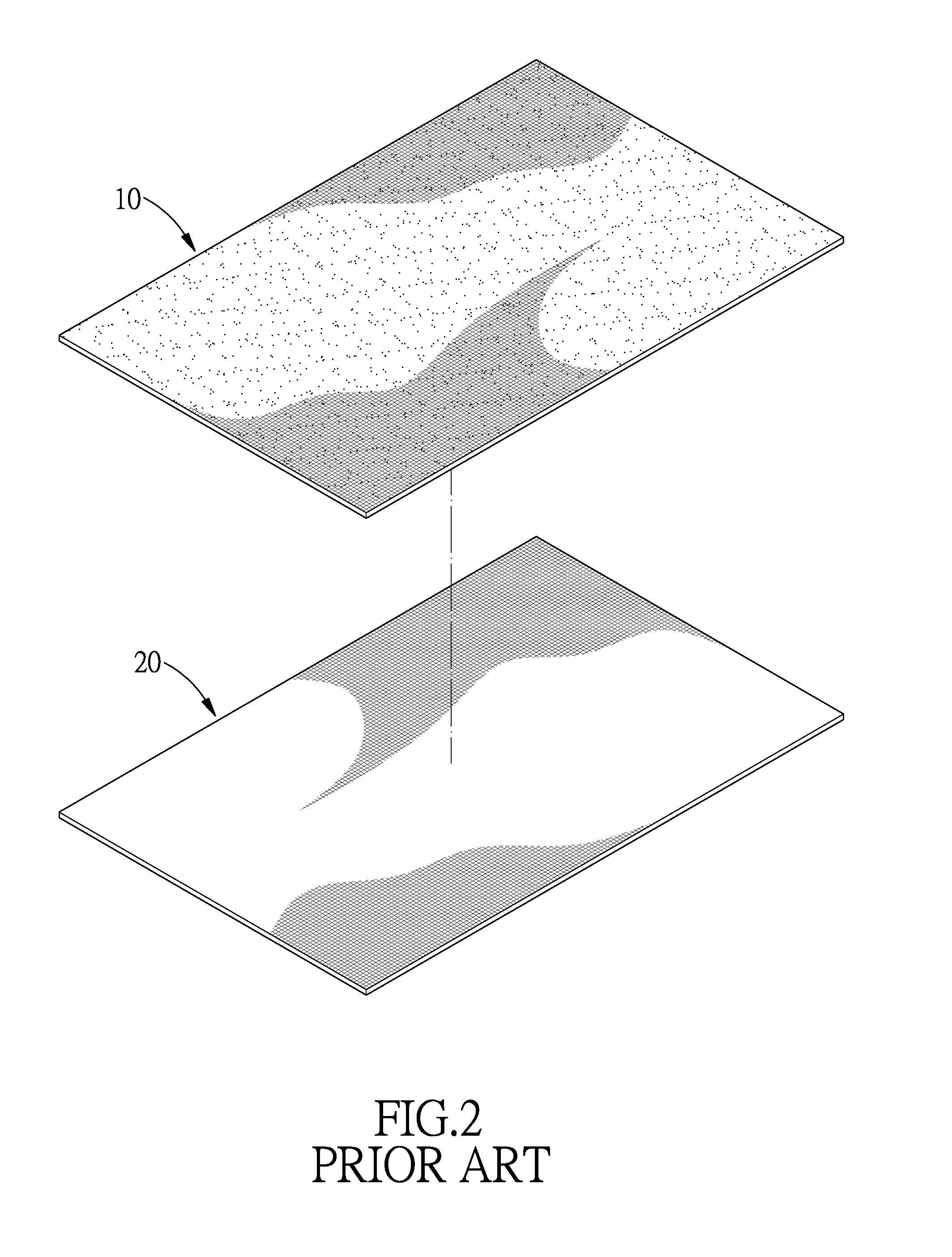
This method for alternatively superimposing the carbon and glass fiber fabric doesn't allow for accurate adjustment of the proportion between the glass fiber and the carbon fiber, and further involves complicated production and assembly procedures and therefore is uneconomical.

Method used


Image

  • Mixed Fiber Structure used on a Bicycle
  • Mixed Fiber Structure used on a Bicycle
  • Mixed Fiber Structure used on a Bicycle

Examples


Embodiment Construction

[0017]The present invention will be clearer from the following description when viewed together with the accompanying drawings, which show, for purpose of illustrations only, the preferred embodiment in accordance with the present invention.

[0018]Referring to FIGS. 3-4, a mixed fiber structure used on a bicycle in accordance with a preferred embodiment of the present invention comprises a plurality of mixed fiber substructures 30 which are coupled in a parallel manner to one another to form a bicycle part. Each of the mixed fiber substructures 30 is made of two different types of fibers, one type of the fibers is carbon fiber 31, all the fibers extend in an axial direction X, and between each two neighboring fibers and between each two neighboring mixed fiber substructures 30 is arranged an adhesive layer.

[0019]In this embodiment, each of the mixed fiber substructures 30 includes a plurality of carbon fibers 31 and a plurality of glass fibers 32 which are alternatively arranged in a...


PUM

PropertyMeasurementUnit
structureaaaaaaaaaa
weightaaaaaaaaaa
structure strengthaaaaaaaaaa

Abstract

A mixed fiber structure used on a bicycle is provided with a plurality of mixed fiber substructures which are coupled in a parallel manner to one another to form a bicycle part, each of the mixed fiber substructures includes a plurality of two types of fibers which are alternatively arranged in a parallel manner and all extend along an axial direction, between each two neighboring fibers and between each two neighboring mixed fiber substructures is arranged an adhesive layer, and one of the two types of fibers is carbon fiber. The proportion between the carbon fiber and the glass fiber can be adjusted according to the special toughness and strength requirements for specific bicycle parts. Furthermore, the carbon and glass fibers are bonded together by the adhesive layer instead of being woven together, so the manufacturing cost of the present invention can also be reduced.

Description

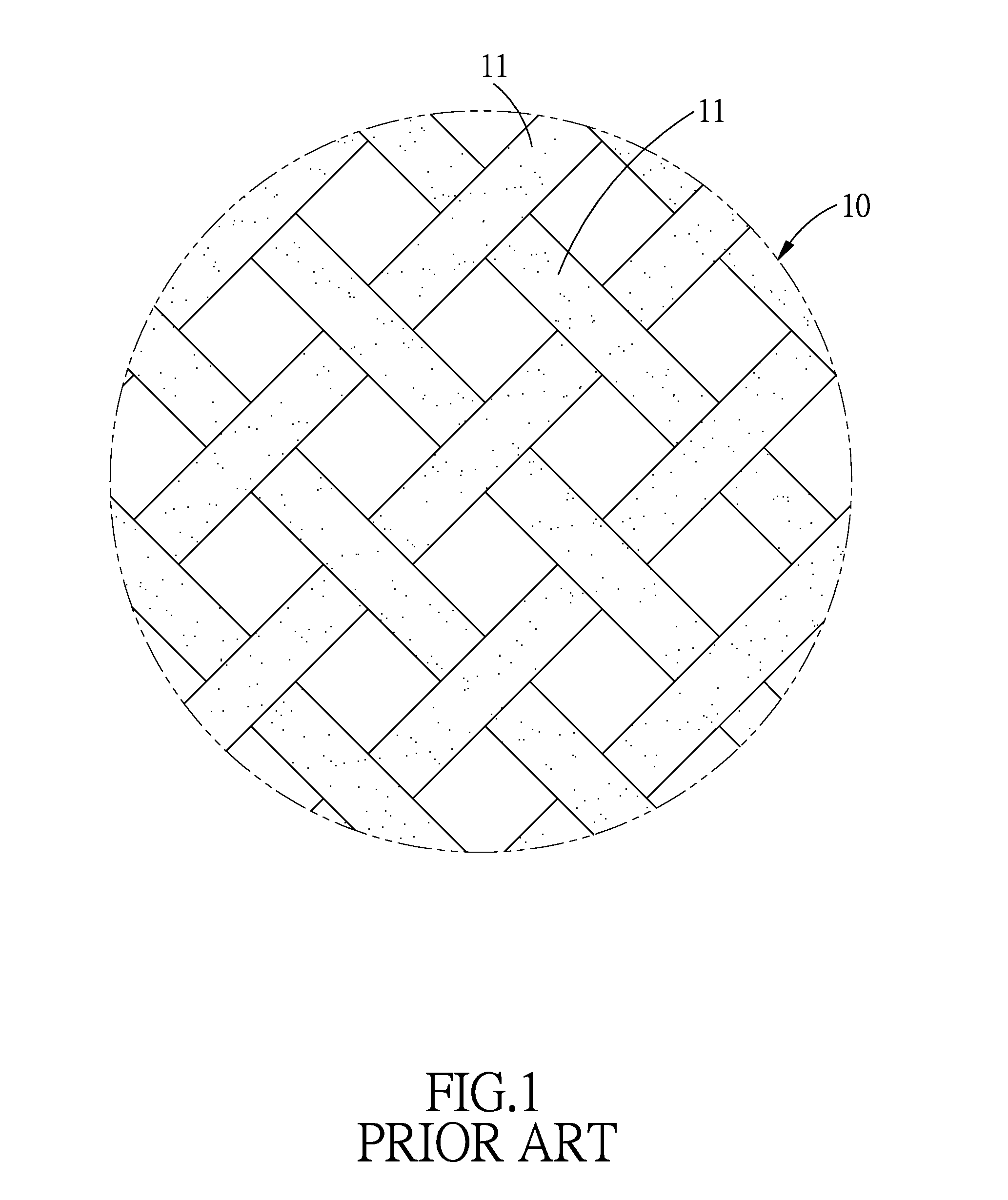
BACKGROUND OF THE INVENTION[0001]1. Field of the Invention[0002]The present invention relates to a mixed fiber structure, and more particularly to a mixed fiber structure used on a bicycle.[0003]2. Description of the Prior Art[0004]Carbon fiber is used in bicycle industry to make products light and strong, due to its light weight and strong structure strength. As shown in FIG. 1, a carbon fiber fabric 10 is woven from a plurality of carbon fibers 11 which are interlaced at right angles to form the carbon fiber fabric 10. Then the carbon fiber fabric 10 can be rolled into a bicycle part, such a tube. However, carbon fiber is very expensive. Furthermore, the structure fully made of carbon fabric may not meet the requirement of toughness and is likely to fracture.[0005]To enhance toughness, bicycle parts manufactures came up with a method to produce the bicycle parts by alternatively superimposing a plurality of layers of carbon fiber fabric 10 and glass fiber fabric 20 together, this ...

Claims


Application Information

Patent Timeline
Patent Type & Authority Applications(United States)
IPC IPC(8): B32B5/12
CPCB32B5/12B32B5/08B62K19/16Y10T428/249924
Inventor YU, CHEN-KAI
Owner GIANT KUNSHAN
Learn More