Catheter with retractable cover and pressurized fluid

a retractable cover and catheter technology, applied in the field of catheters, can solve the problems of increasing friction, unable to deploy the stent, damage to the integrity of the coated surface material of the stent, etc., and achieve the effects of shortening the stent, reducing axial friction forces, and low axial rigidity

Active Publication Date: 2014-01-30
MEDINOL LTD
View PDF4 Cites 5 Cited by
  • Summary
  • Abstract
  • Description
  • Claims
  • Application Information

AI Technical Summary

Benefits of technology

[0005]Another problem in the art arises with stents having relatively low axial rigidity, where axial friction forces applied during deployment or mounting of the stent on the catheter system may shorten the stent. It is therefore advantageous to have a catheter system that minimizes axial friction forces applied to the stent during deployment and mounting.

Problems solved by technology

One problem that arises when mounting the stent on the catheter system as well as during retraction of the sheath is excessive friction and rubbing between the sheath and the stent that may complicate and sometimes render stent deployment impossible.
Excessive friction and rubbing between the stent and the constraining sheath may cause damage to the integrity of the coated surface material of the stent by the friction between the sheath and the external surface of the stent.
Moreover, such friction tends to increase even more when using longer stents or stents with a narrower crimping profile.
Another problem in the art arises with stents having relatively low axial rigidity, where axial friction forces applied during deployment or mounting of the stent on the catheter system may shorten the stent.
Yet another problem known in the art is related to the size of the proximal portion or the handle of catheter systems of self-expandable stents.
When using longer stents (i.e. 100 millimeters and more) this limitation becomes a disadvantage as it leads to relatively long handles with a bulky mechanical structure that may be uncomfortable to operate.

Method used


Image

  • Catheter with retractable cover and pressurized fluid
  • Catheter with retractable cover and pressurized fluid
  • Catheter with retractable cover and pressurized fluid

Examples


Embodiment Construction

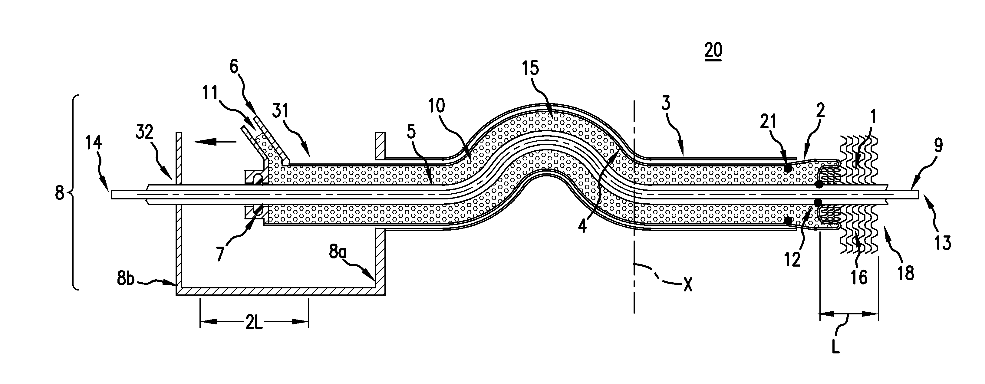
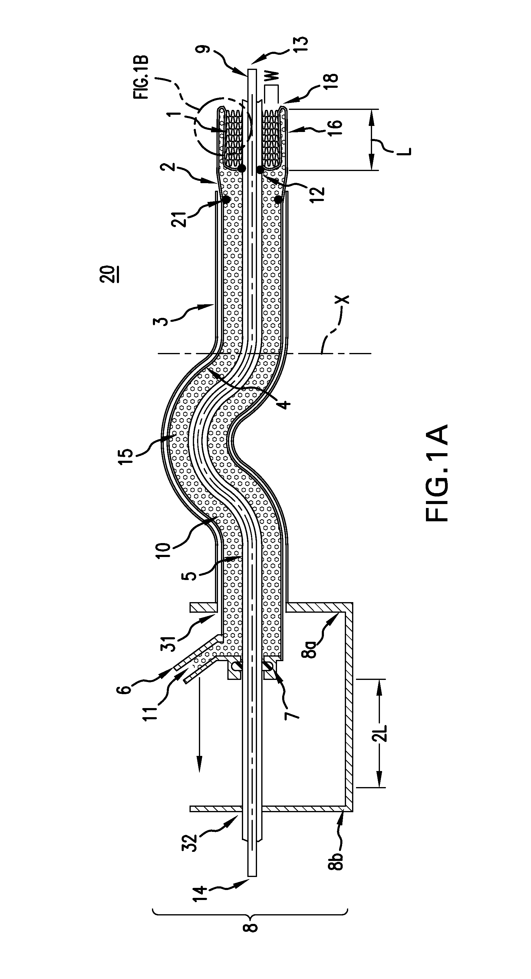
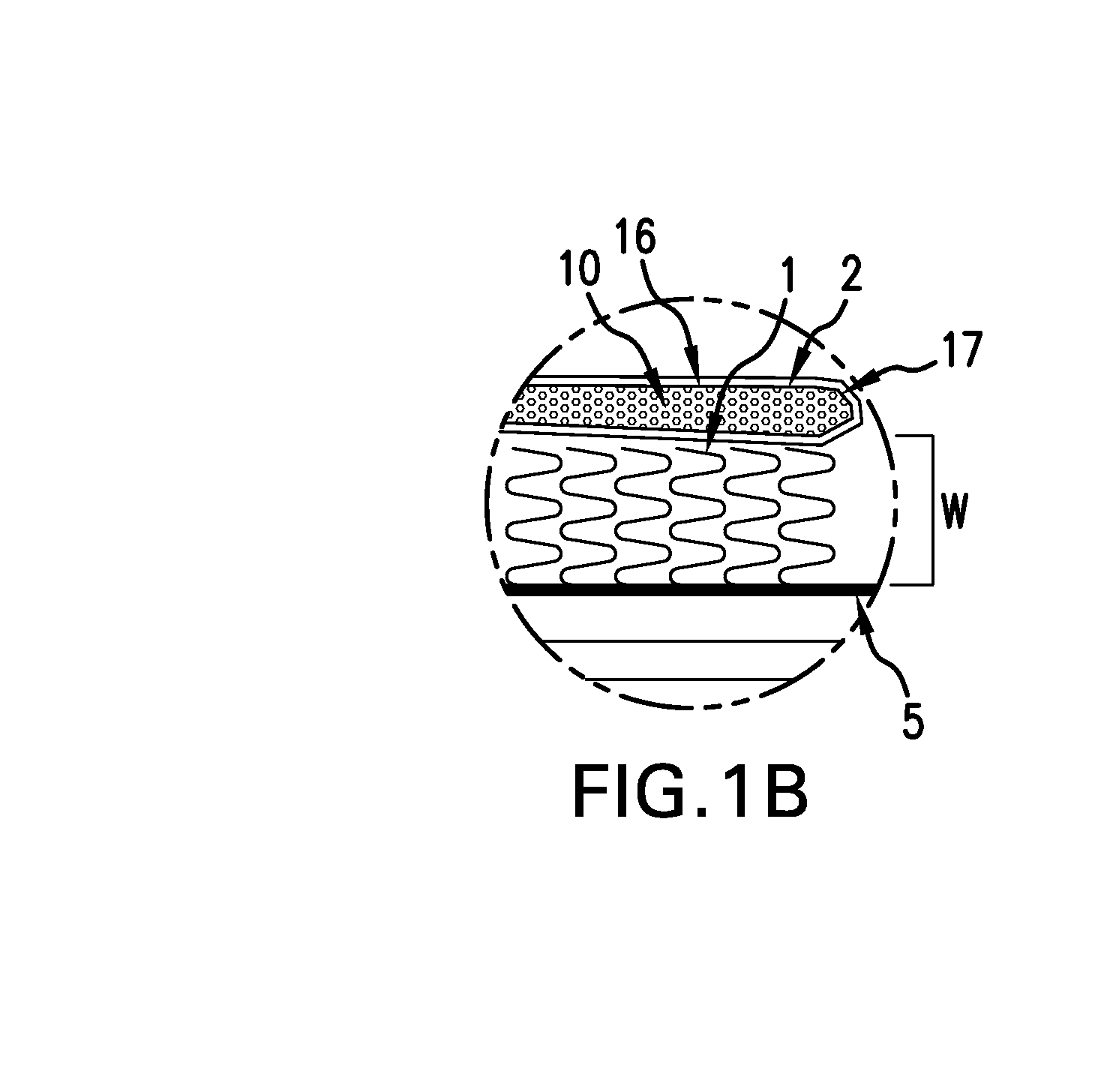
[0022]The catheter system with a retractable sleeve structure of the invention allows an intravascular device to be delivered to a target vessel without subjecting the device to frictional forces during deployment associated with other delivery systems using a constraining sheath. The catheter system of the invention includes an elongate inner tube defining proximal and distal ends and a lumen extending longitudinally therethrough wherein a guide wire is movably disposed. The catheter system further includes an elongate outer tube having a proximal and a distal end, wherein the inner tube coaxially extends therethrough along the entire length. The inner tube and outer tube are affixed to a housing structure in the proximal portion of the catheter system, the housing structure includes a distal opening to which the outer tube is affixed, as well as a proximal opening to which the inner tube is affixed. “Distal” is defined herein as being closer to the insertion end of the catheter (i...


PUM


Abstract

Apparatus and method for delivering and deploying an intravascular device into the vessel including an outer and inner tube that are axially linked by a housing structure at the proximal end of the catheter, and a retractable sleeve structure having a middle tube and sleeve tip. The sleeve tip is sealed to the inner tube at the distal end, and continuously extends into the middle tube. At the proximal end of the sleeve structure, the middle tube is sealed to either a housing structure or slideable proximal ring, forming a sealed chamber between the inner tube and the sleeve structure. A radial space is formed between the sleeve tip and the inner tube optimized for intravascular device placement. During retraction of the sleeve structure, the fold of the sleeve tip peels away from the device, which expands to its deployed state while minimizing axial forces and friction.

Description

FIELD OF THE INVENTION[0001]The present invention relates to the field of catheters, in particular a catheter system with a retractable sleeve structure for use, for example, in delivery and deployment of an intravascular device. The catheter system is specifically designed for use in the delivery of an intravascular device through tortuous vessels and its deployment therein.BACKGROUND[0002]Transluminally implantable intravascular devices, such as stents or grafts, are initially mounted upon or within a delivery catheter and then crimped into a compact configuration of a relatively small diameter to facilitate insertion and transluminal advancement of the device into the desired lesion requiring treatment. Thereafter, such devices are radially expanded to a larger operative diameter either by removing a constraining layer thereby releasing the device or by inflating a balloon on which the device is crimped. When expanded the device serves to support the vessel against its tendency t...

Claims


Application Information

Patent Timeline
Patent Type & Authority Applications(United States)
IPC IPC(8): A61M25/14A61M25/01
CPCA61F2/966A61F2250/0003A61F2/9522A61F2/9517A61F2/95
Inventor COHEN, ITSHAKMAXIMUK, SHAHARMOISEYEV, GILAD
Owner MEDINOL LTD
Why Eureka
Try Eureka