Photon turbine generator for power generation

a photon turbine and power generation technology, applied in the direction of electric generator control, machines/engines, therapy, etc., can solve the problems that the photon turbine eventually ceases to operate, and achieve the effect of high circulating power, high quality, and maximum number of photon bounces

Inactive Publication Date: 2014-02-06
CAMPBELL BRIAN
View PDF1 Cites 16 Cited by
  • Summary
  • Abstract
  • Description
  • Claims
  • Application Information

AI Technical Summary

Benefits of technology

[0008]In order to overcome these and other weaknesses, drawbacks, and deficiencies in the known art, it is the aim of the present disclosure to describe a Photon Turbine Generator (PTG) to harness radiation pressure to perform useful work in an Earth-based or macroscopic application (although the PTG can be used in space and on a microscopic scale as well). Under suitable conditions, radiation pressure can provide the motive force for a power generator. One key to making radiation pressure a worthwhile motive force for a power generator is to recycle the EM radiation, thereby maximizing the number of photon bounces off of mirrors or other reflective surfaces. This recycling of photons may be accomplished with a resonant cavity or a waveguide. Thus, a low power input laser beam may achieve a high circulating power inside the cavity or waveguide. With mirrors or reflective surfaces of sufficiently high quality, the power amplification inside of a resonant cavity or closed-loop waveguide can enable the PTG to produce more power than it consumes for a temporary period of time. This time period would be determined primarily by the lifetime of the input laser. For example, a laser pumping mechanism and gain medium allowing for 500,000 hours of continuous operation before degrading or expiring would enable the PTG to operate continuously for 500,000 hours, assuming the other components of the PTG (e.g., bearings, field windings) are well maintained and operate properly.

Problems solved by technology

After start up, if left to itself, the PTG would eventually cease operating, due to the gradual degradation of the laser pumping mechanism or gain medium, as well as the normal wear and tear of other key components.

Method used


Image

  • Photon turbine generator for power generation
  • Photon turbine generator for power generation
  • Photon turbine generator for power generation

Examples


Embodiment Construction

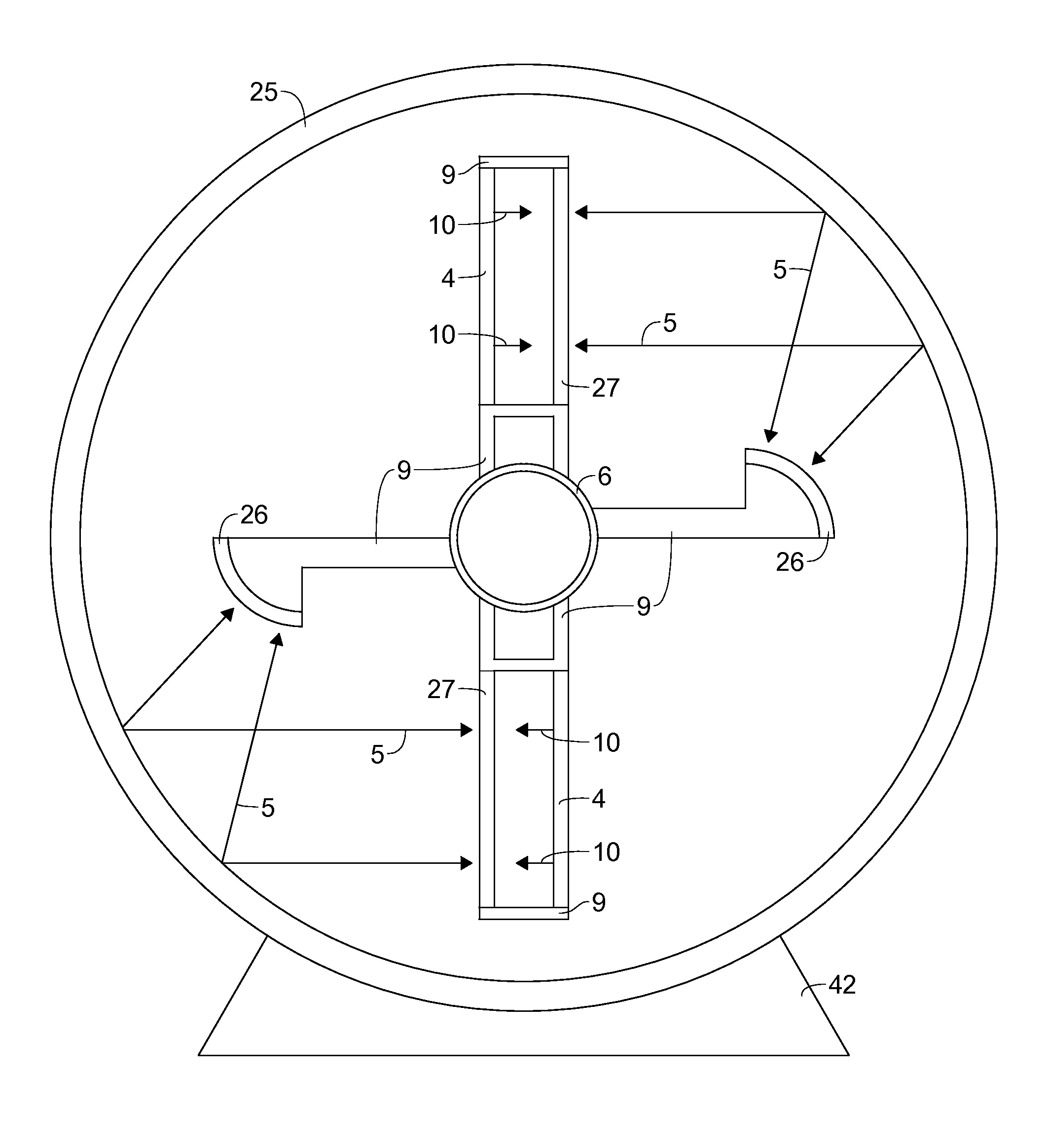
[0079]In the descriptions of the drawings and preferred embodiments, the term “photon turbine” is used to refer to the portion of the Photon Turbine Generator (PTG) that includes the resonant cavities or waveguides; any mechanisms, devices, or systems that support the resonators or waveguides; and the surrounding structure in which the resonant cavities or waveguides are located, such as the fairing and the components located inside of the fairing. The term Photon Turbine Generator, or PTG, comprises the photon turbine, the electrical generator coupled to the photon turbine, and any equipment that supports, regulates, or monitors the photon turbine or electrical generator.

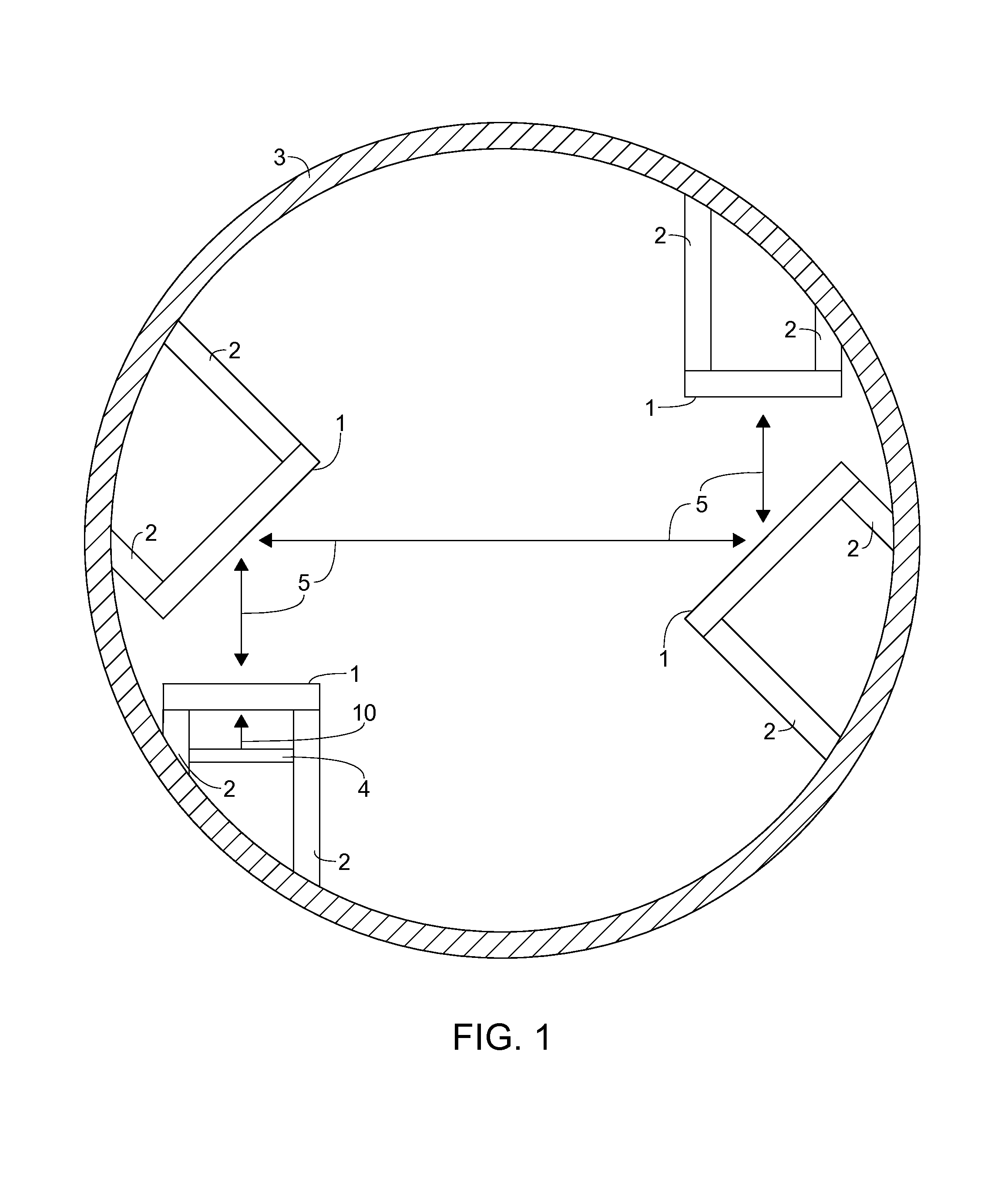
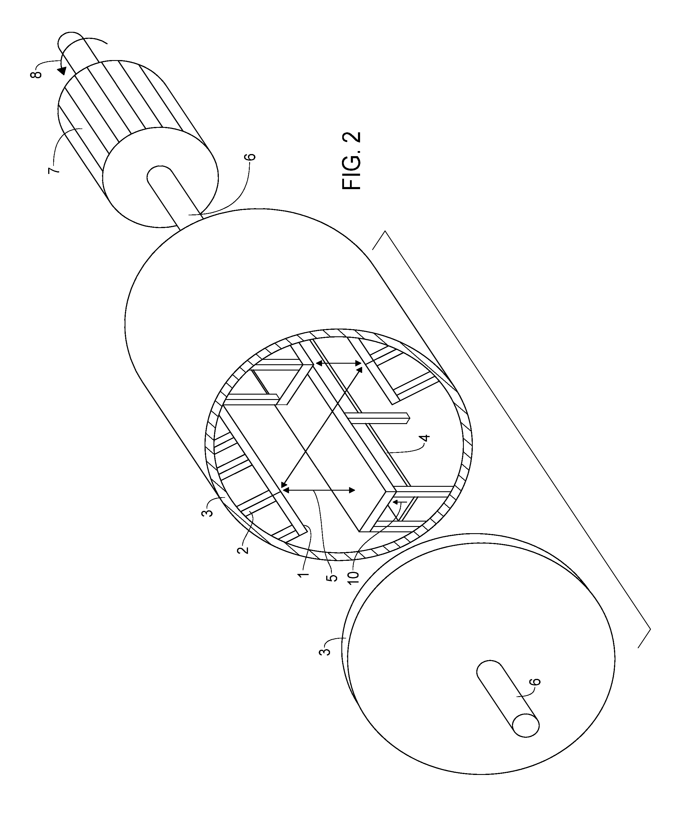
[0080]FIG. 1 shows a cross-sectional view of a Photon Turbine Generator (PTG) using a simple, Z-shaped, folded resonator design. Four mirrors 1 are supported on mounts 2 within a cylindrical structure 3, which will be subjected to torques in a manner broadly similar to a squirrel cage or hamster wheel. The force du...


PUM


Abstract

A method and device for generating power using radiation pressure is described. The device comprises a turbine generator in which the turbine comprises optical resonant cavities or waveguides. The turbine rotates as a result of the force applied to the resonant cavities or waveguides by the radiation pressure of the circulating laser beam. Because of the amplification of the power of the input laser beam through resonant enhancement, the Photon Turbine Generator (PTG) has the potential for overunity efficiency (i.e., power output exceeding power input), lasting until the laser pumping mechanism or gain medium degrades or expires. The PTG may be built on either a macroscopic or microscopic scale. The PTG can provide clean, efficient, long-lasting power for diverse applications (e.g., energy, transportation, and electronic devices), while also supplying electricity to meet its own operational needs (e.g., laser pump power).

Description

BACKGROUND[0001]1. Field of the Disclosure[0002]This invention relates to a system and method of generating motive power, and more specifically to a system and method of generating motive power that uses radiation pressure to apply mechanical force to a turbine comprising one or more optical resonant cavities or waveguides.[0003]2. Brief Discussion of Related Art[0004]When electromagnetic (EM) radiation interacts with matter, it imparts a very small physical force onto it, which is known as radiation pressure (also known as photon pressure or light pressure). This force is approximately 6.67 newtons per gigawatt of EM radiation, assuming the photons are reflected rather than absorbed, and is independent of the wavelength of the EM radiation. Radiation pressure was first demonstrated experimentally in 1900 by P. N. Lebedev, whose findings confirmed James Clerk Maxwell's theory that EM waves exert radiation pressure.[0005]Radiation pressure is not a particularly well known subject out...

Claims


Application Information

Patent Timeline
Patent Type & Authority Applications(United States)
IPC IPC(8): G21K5/00F02D29/06F01D15/10
CPCF03G6/00Y02E10/46
Inventor CAMPBELL, BRIAN
Owner CAMPBELL BRIAN
Why Eureka
Try Eureka