Power switchgear cabinet of a device for producing electric energy

Active Publication Date: 2014-02-06
CONVERTERTEC DEUT GMBH
View PDF10 Cites 27 Cited by
  • Summary
  • Abstract
  • Description
  • Claims
  • Application Information

AI Technical Summary

Benefits of technology

[0059]The mains connection switch cabinet preferably has an auxiliary voltage supply and/or a mains switch. The auxiliary voltage supply preferably generates a single-phase 230 V alternating voltage from the mains alternating current. Any direct and/or alternating voltages are conceivable, however. It is similarly possible to feed in the auxiliary voltage from outside, so that in this case the auxiliary voltage supply in the mains connection cabinet merely serves as a distribution node for the power switch cabinets. The auxiliary voltage can thus be provided for all power switch cabinets in a simple manner. By means of one or a plurality of mains switches all power switch cabinets can be easily isolated from the mains.
[0060]The central control unit and the decentralised control units are preferably designed in such a way that the central control unit and the decentralised control units can be connected together by means of fibre optics. In this way the number of cabled connections required is reduced, further simplifying the installation and scalability. With the use of fibre optics signals fault due to possible high frequency spurious pulses are avoided.
[0061]The object set out above is achieved in particular by a device for producing electric energy which has a power switch cabinet according to the invention or a switch cabinet arrangement comprising a power switch cabinet according to the invention. As already stated, by means of a power switch cabinet according to the invention a cost-saving, compact construction with minimal connection paths between the components and as a resu

Problems solved by technology

Furthermore, because of the high powers required additional challenges are posed by the need for cooling with a simultaneously compact design of the switch cabinet.
In order to connect the power electronics part to the rest of the frequency converter, complicated and costly connectors are required.
The result of this is complicated cabling and a high space requirement.
The disadvantage of this, however, is that the in

Method used


Image

  • Power switchgear cabinet of a device for producing electric energy
  • Power switchgear cabinet of a device for producing electric energy
  • Power switchgear cabinet of a device for producing electric energy

Examples


Embodiment Construction

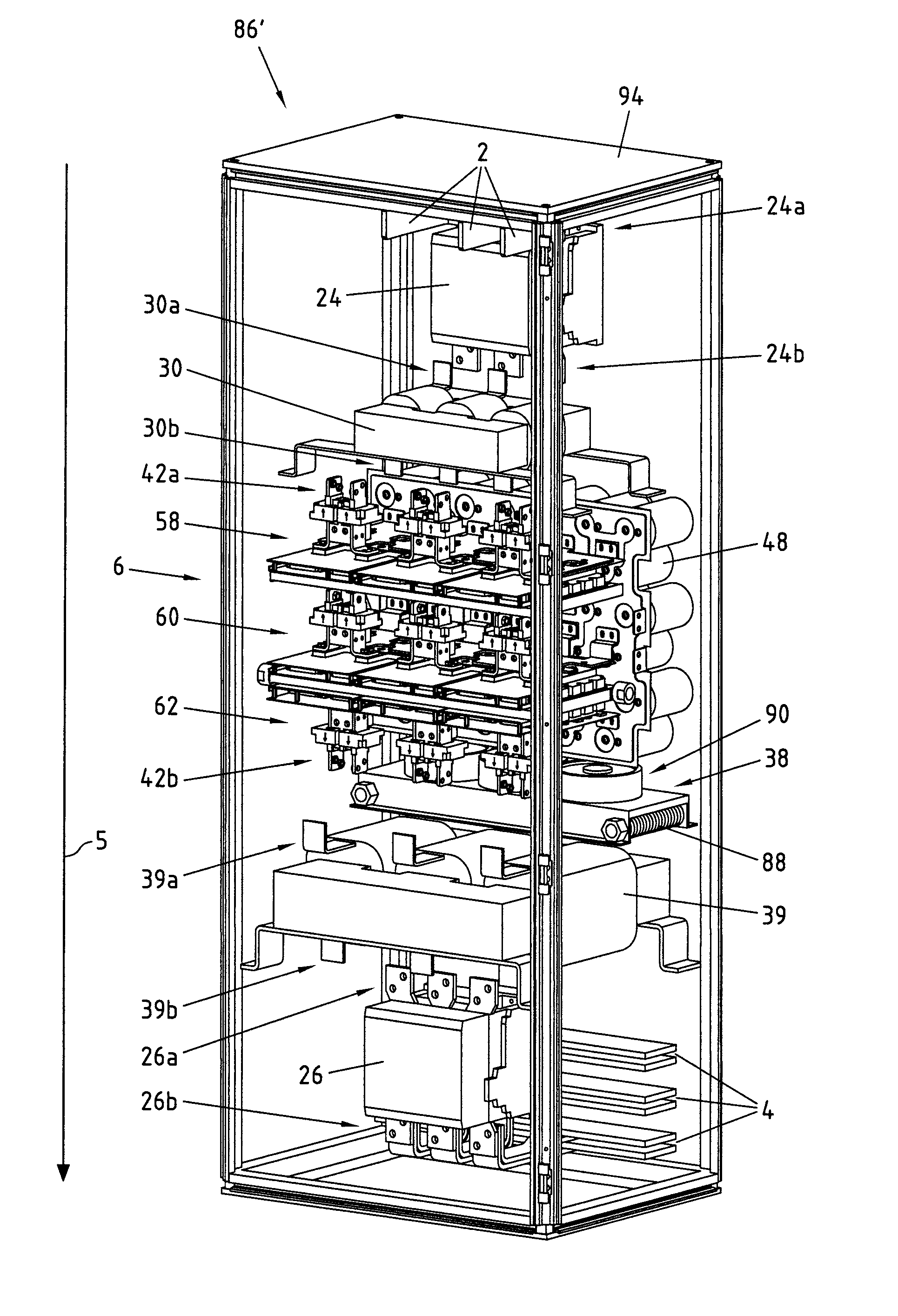
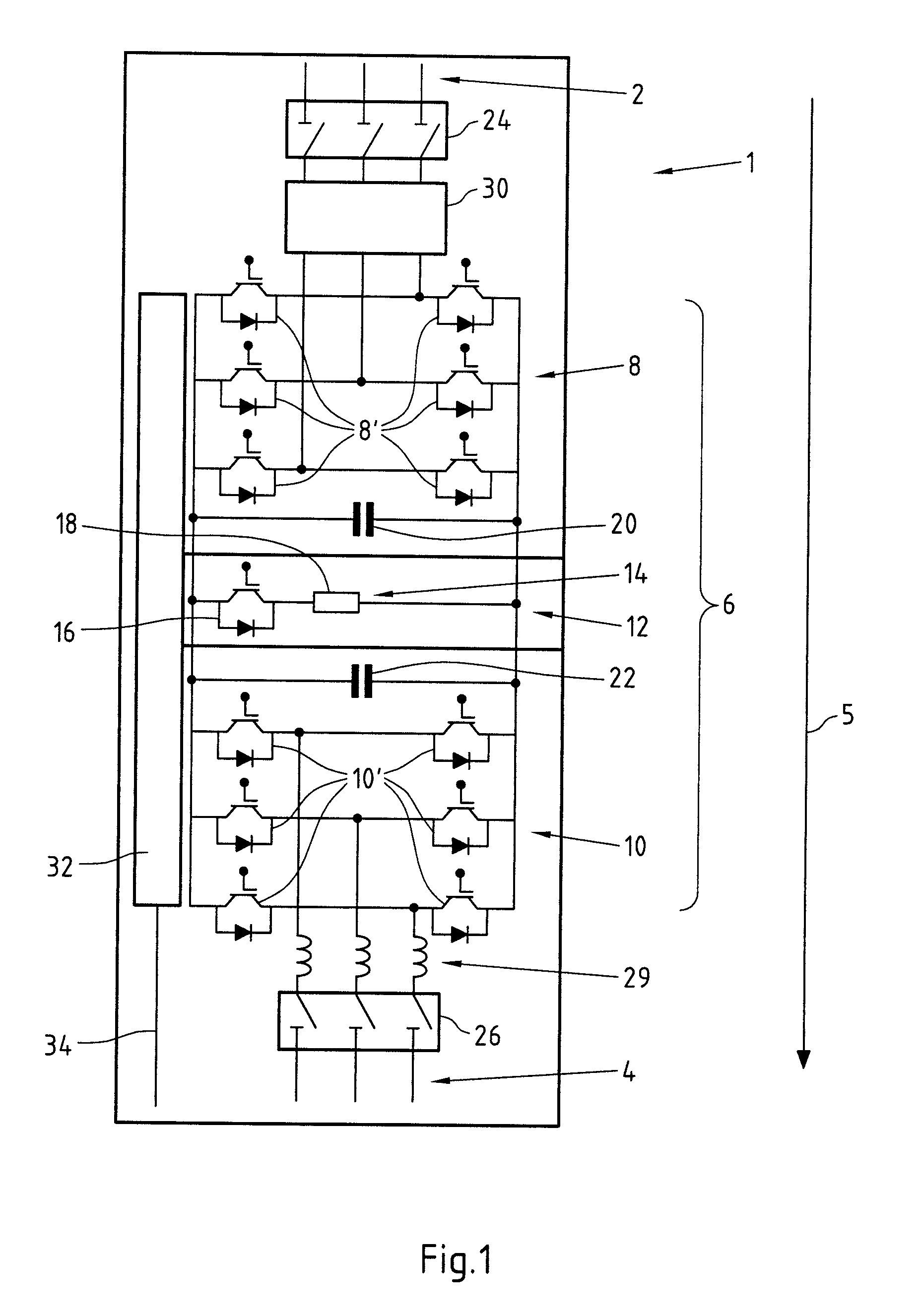
[0074]FIG. 1 is a schematic in the form of a circuit diagram of the design of an exemplary embodiment of a power switch cabinet 1. As the circuit diagram shows, the power switch cabinet 1 at a first end has a machine connection 2 and at a second end a mains connection 4. In this exemplary embodiment, both connections 2, 4 have a three-wire design for the provision of three-phase power. These connections 2, 4 can be created using cables or AC rails, preferably copper rails. Here the power is transported from the machine connection 2 at the first end of the switch cabinet 1 in the direction of power flow, shown by the arrow 5, via the components described in the following and connected in series to the mains connection 4 at the second end of the power switch cabinet 1 in a vertical direction from top to bottom.

[0075]Via the machine connection 2 a plurality of switch cabinets 1 can be connected in parallel and have an electrically conductive connection with a generator 68, for example ...


PUM


Abstract

The invention relates to a power switch cabinet of a device for producing electric energy. The technical object of obtaining optimum scalability and cooling of a power switch cabinet despite little space being required is achieved according to the invention in that the power switch cabinet has a machine connection, a power module and a mains connection, wherein the power module has a machine converter, a mains converter, a direct voltage intermediate circuit and a chopper, and the arrangement of the components substantially corresponds to the direction of the power flow.

Description

CROSS-REFERENCE TO RELATED PATENT APPLICATIONS[0001]This patent application is a continuation of pending PCT Application No. PCT / EP2012 / 056220, filed Apr. 4, 2012, which claims the benefit of German Application No. 102011001786.0, filed Apr. 4, 2011, the entire teachings and disclosure of which are incorporated herein by reference thereto.FIELD OF THE INVENTION[0002]The invention relates to a power switch cabinet of a device for producing electric energy.BACKGROUND OF THE INVENTION[0003]Arranging electronic components, such as converters or filters, in particular devices for producing electric energy, in power switch cabinets is known from the prior art. Wind turbines are often fitted with double-fed asynchronous generators, since in this way only part of the output has to be transported via the converters of the turbine. At speeds below the synchronous speed of the generator the efficiency of the turbine drops, however. Therefore synchronous generators with full-power converters ar...

Claims


Application Information

Patent Timeline
IPC IPC(8): H02B13/02H05K7/20
CPCH05K7/2039H02B13/02H02M7/003H02M7/493F03D9/25F03D9/257F03D80/82H02J2300/28H02J3/381Y02E10/76Y02E10/72H05K7/14325H05K7/1432H02B1/32H02B1/565
Inventor EICHLER, MARKUSNOWAK, HANS-GEORGHITPAMARIANNE
Owner CONVERTERTEC DEUT GMBH
Why Eureka
Try Eureka