In vivo bioluminescence monitoring apparatus

a bioluminescence and monitoring apparatus technology, applied in the field of in vivo bioluminescence monitoring apparatus, can solve the problems of preventing anesthesia (and thus long exposure time) of the animals under investigation, signal can only be detected for a few minutes at most, and the prior art cannot be applied to experimental conditions where bioluminescence is expressed, etc., to achieve minimal background noise and high temporal resolution

Active Publication Date: 2014-02-13
UNIVERSITY OF GENEVA
View PDF8 Cites 6 Cited by
  • Summary
  • Abstract
  • Description
  • Claims
  • Application Information

AI Technical Summary

Benefits of technology

[0010]An object of this invention is to provide an apparatus for real-time in vivo bioluminescence and / or fluorescence monitoring in a small animal allowing a high temporal resolution, with a minimal background noise.

Problems solved by technology

Yet, frequent image acquisition over extended time periods (several days) are required in such studies, and this obviously precludes anesthesia (and thus long exposure times) of the animals under investigation.
Moreover, conventional fluorescence measurements imply excitation with bright light, which would be likely to phase-shift animals during the recording.
However, the signal can only be detected for a few minutes at most.
Despite its usefulness, the technology of the prior art cannot be applied to experimental conditions where bioluminescence is expressed in tissues containing a small number of cells, such as skin, skeletal and heart muscle, kidney, parts of the intestine, spleen, and exocrine pancreas, nor does it allow the long-term monitoring of circadian gene expression in tissues of freely moving individual animals for instance.
With the technology of the prior art, signal strength may be a limiting factor as well as the duration of the monitoring of the bioluminescence signal.
Moreover, the technology of the prior art does not allow to study the effect of controlled environmental conditions including food, light, medicaments, etc.

Method used


Image

  • In vivo bioluminescence monitoring apparatus
  • In vivo bioluminescence monitoring apparatus
  • In vivo bioluminescence monitoring apparatus

Examples


Embodiment Construction

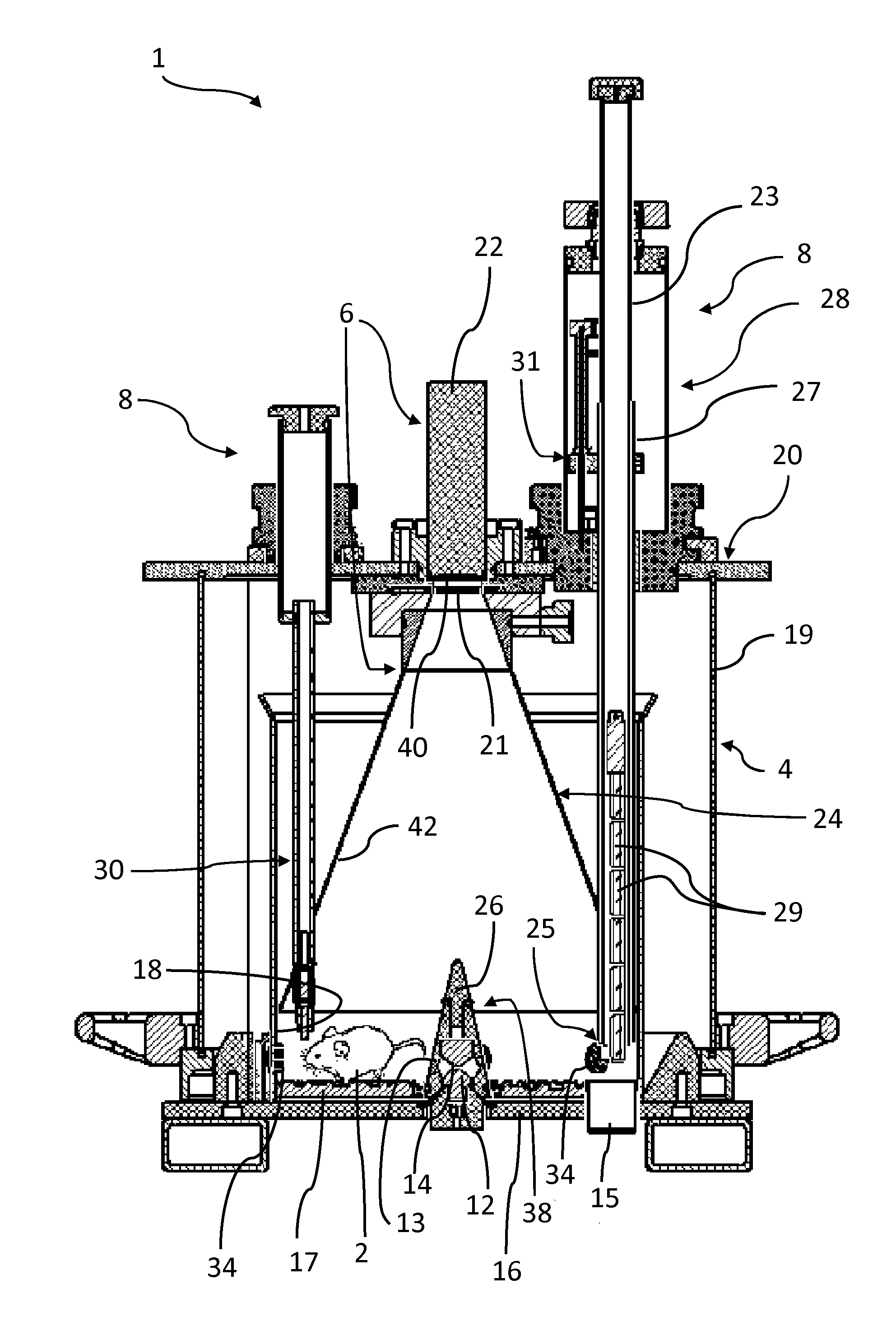
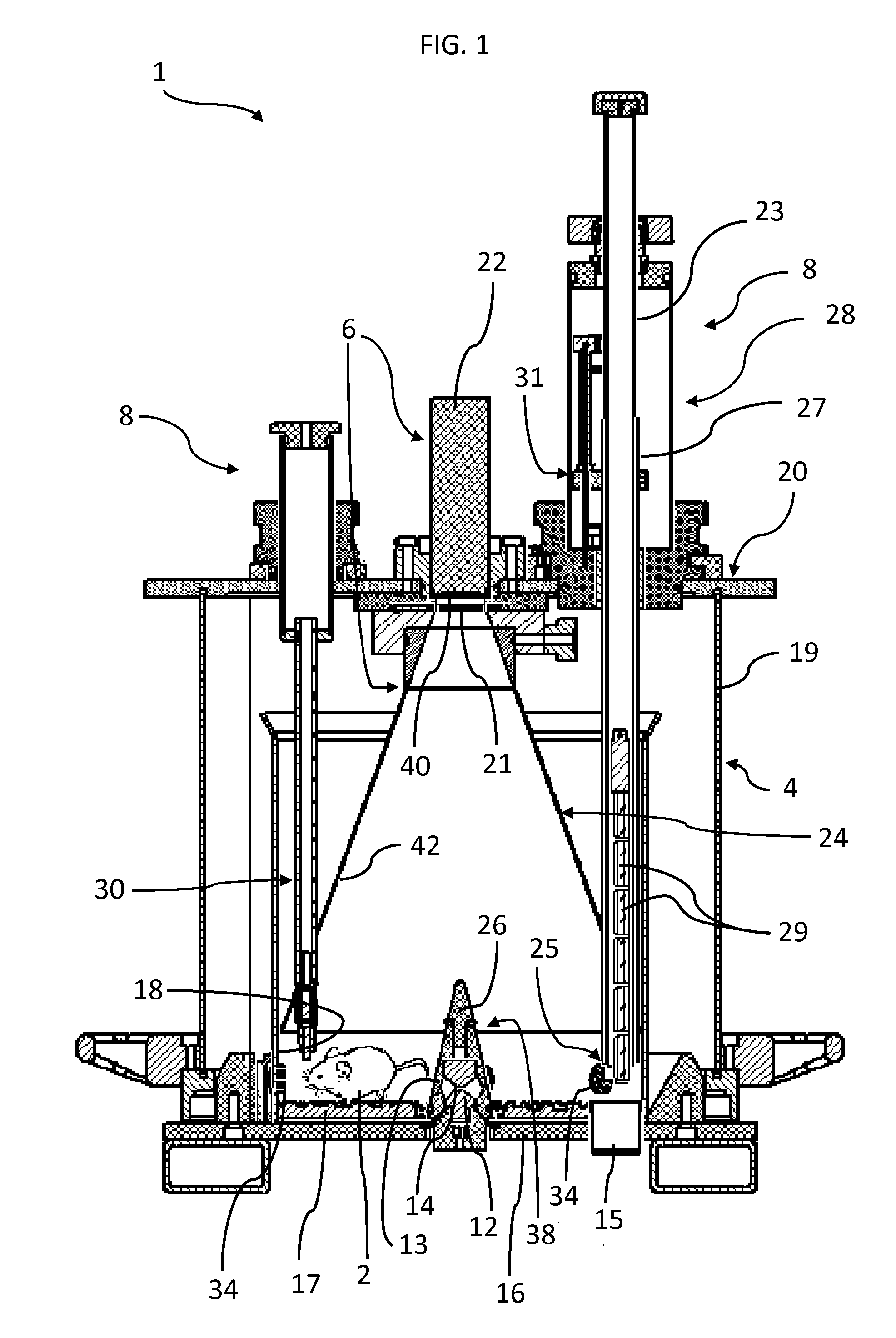
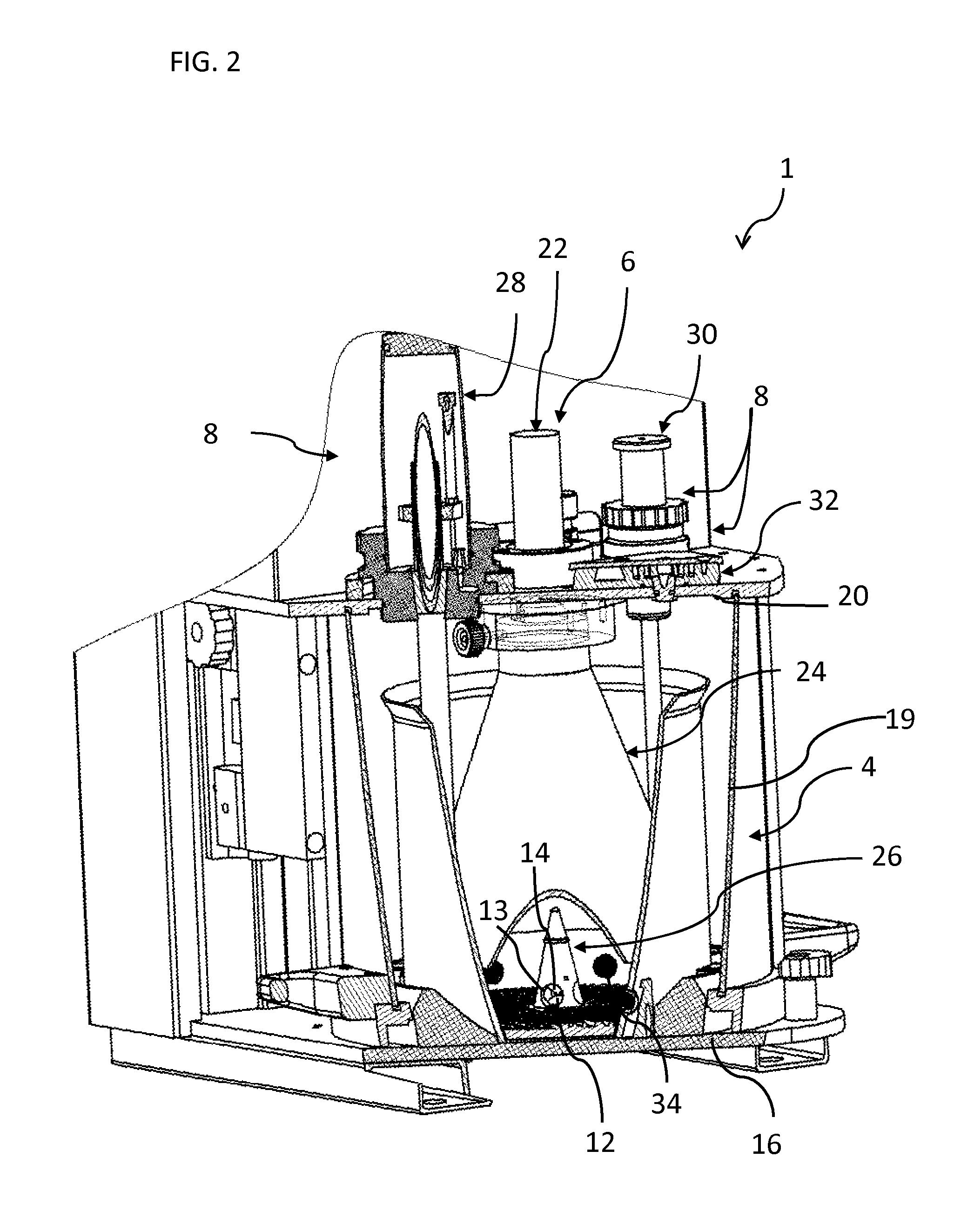
[0034]Referring to the figures, an apparatus 1 for real-time in vivo bioluminescence monitoring in a small animal 2 comprises a light-tight enclosure 4, a bioluminescence detector system 6, and a life sustaining and controlling system 8 to enable monitoring bioluminescence from the small animal (e.g a rodent) over an extended period of time, for example from a few days up to a few weeks. The apparatus 1 may also be used for real-time in vivo fluorescence monitoring and measurement. For the sake of simplicity, referral to the term “bioluminescence monitoring” in the present description shall generally be understood to include “bioluminescence and / or fluorescence monitoring” unless the context dictates otherwise.

[0035]The small animal expresses a luminescent reporter gene under the control of a gene of interest. The luminescent reporter gene may in particular include a gene encoding luciferase, for instance firefly luciferase. The small animal may in particular be a transgenic animal ...


PUM


Abstract

Apparatus for real-time in vivo bioluminescence monitoring in a conscious small animal, comprising a light-tight enclosure (4) with a base (16), side wall (19) and cover (20) configured for housing the small animal such that it may move freely, a bioluminescence detector system (6) comprising a light detector (22) for detecting the light emitted by said small animal connected to a data processing system, and a life sustaining system (8) configured for maintaining the small animal alive for a prolonged period of time spanning from a few days to a few weeks.

Description

FIELD OF INVENTION [0001]This invention relates to an apparatus and a method for non-invasive real-time in vivo bioluminescence monitoring in a small animal.BACKGROUND [0002]In many biomedical fields it is required to record acute signaling events which reflect biological pathways or mechanisms. One common method to monitor gene expression in a living cell, tissue, or animal, relies on the use of a luminescent reporter gene placed under the control of a gene of interest in said cell, tissue or animal. The activity of genes can be visualized in real-time either by fluorescence or bioluminescence recording of transgenic cells or organisms expressing fluorescent proteins or luciferase, respectively.[0003]Both of these techniques have been successfully adapted to whole-body imaging of mice (Hoffman and Yang (2006) Nat. Protoc 1, 1429-1438; Sandhu et al. (2010) Wiley Interdiscip Rev Syst Biol Med 2, 398-421). However, in most applications the animals were anesthetized to allow for long e...

Claims


Application Information

Patent Timeline
Patent Type & Authority Applications(United States)
IPC IPC(8): A61B5/00
CPCA61B5/0059A01K1/031A01K29/005G01N21/763
Inventor SCHIBLER, UELILIANI, ANDRESAINI, CAMILLEBONACINA, LUIGIWOLF, JEAN-PIERRE
Owner UNIVERSITY OF GENEVA
Why Eureka
Try Eureka