Switch mode power converter current sensing apparatus and method

a technology of power converter and current sensing apparatus, which is applied in the direction of electric variable regulation, process and machine control, instruments, etc., can solve the problems of limited drawing of current drawn from a source, limited usb 3.0 connection, so as to reduce the loss of sensing components in operation, reduce the overall sensing circuitry in die area, and reduce the effect of loss of sensing components

Active Publication Date: 2014-02-20
TEXAS INSTR INC
View PDF8 Cites 33 Cited by
  • Summary
  • Abstract
  • Description
  • Claims
  • Application Information

AI Technical Summary

Benefits of technology

[0006]In certain embodiments, the power FET and the all the FETs in the sensing circuit are constructed using a corresponding integer number of matched transistor units formed in a semiconductor body of an integrated circuit. These integer numbers are chosen in such a way that both the sensing ratio and sensing accuracy can be relatively high and the overall sensing circuitry can be small in die area. Thus, the sensing component loss in operation can be significantly reduced compared with conventional use of series-connected sensing devices, and the die and / or circuit board area dedicated to current sensing components can be reduced.

Problems solved by technology

In many instances, the current drawn from a source may need to be limited, for example, according to specifications published for devices drawing power from a USB connection.
For instance, portable devices are limited to drawing at most 100 mA from a USB 2.0 connection, unless a higher limit (e.g., up to 500 mA) is negotiated.
Similarly, USB 3.0 connections are typically limited to drawing 150 mA unless a higher amount (e.g., up to 900 mA) is negotiated.
However, the conventional current sensing approach incurs significant power loss in terms of heat generated by conduction of high-side current flowing through the sensing device.
Moreover, the sensing component (e.g., resistor or FET) must be sized to accommodate the maximum level of input current, and accordingly the sensing device occupies a significant amount of space in terms of integrated circuit die area and / or external board area, thereby increasing cost.

Method used


Image

  • Switch mode power converter current sensing apparatus and method
  • Switch mode power converter current sensing apparatus and method
  • Switch mode power converter current sensing apparatus and method

Examples


Embodiment Construction

[0016]One or more embodiments or implementations are hereinafter described in conjunction with the drawings, wherein like reference numerals are used to refer to like elements throughout, and wherein the various features are not necessarily drawn to scale. The present disclosure provides solutions for reducing power loss, circuit size, and cost of current sensing in power conversion circuitry, and is hereinafter illustrated and described in the context of power management integrated circuits for operating portable electronic devices and / or for charging batteries thereof. However, the concepts of the present disclosure may be employed in a variety of applications, wherein the disclosure is not limited to the illustrated or described examples.

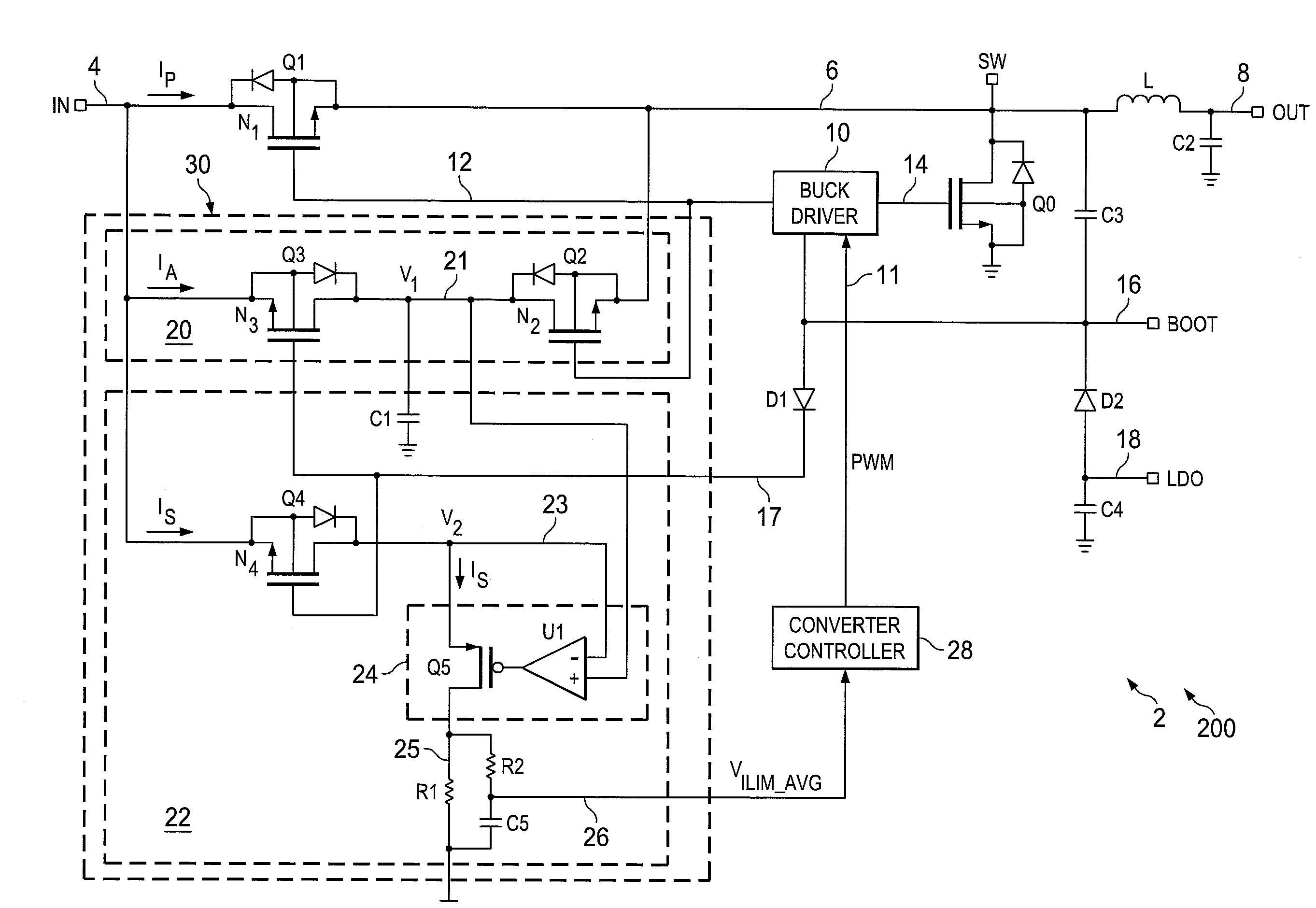
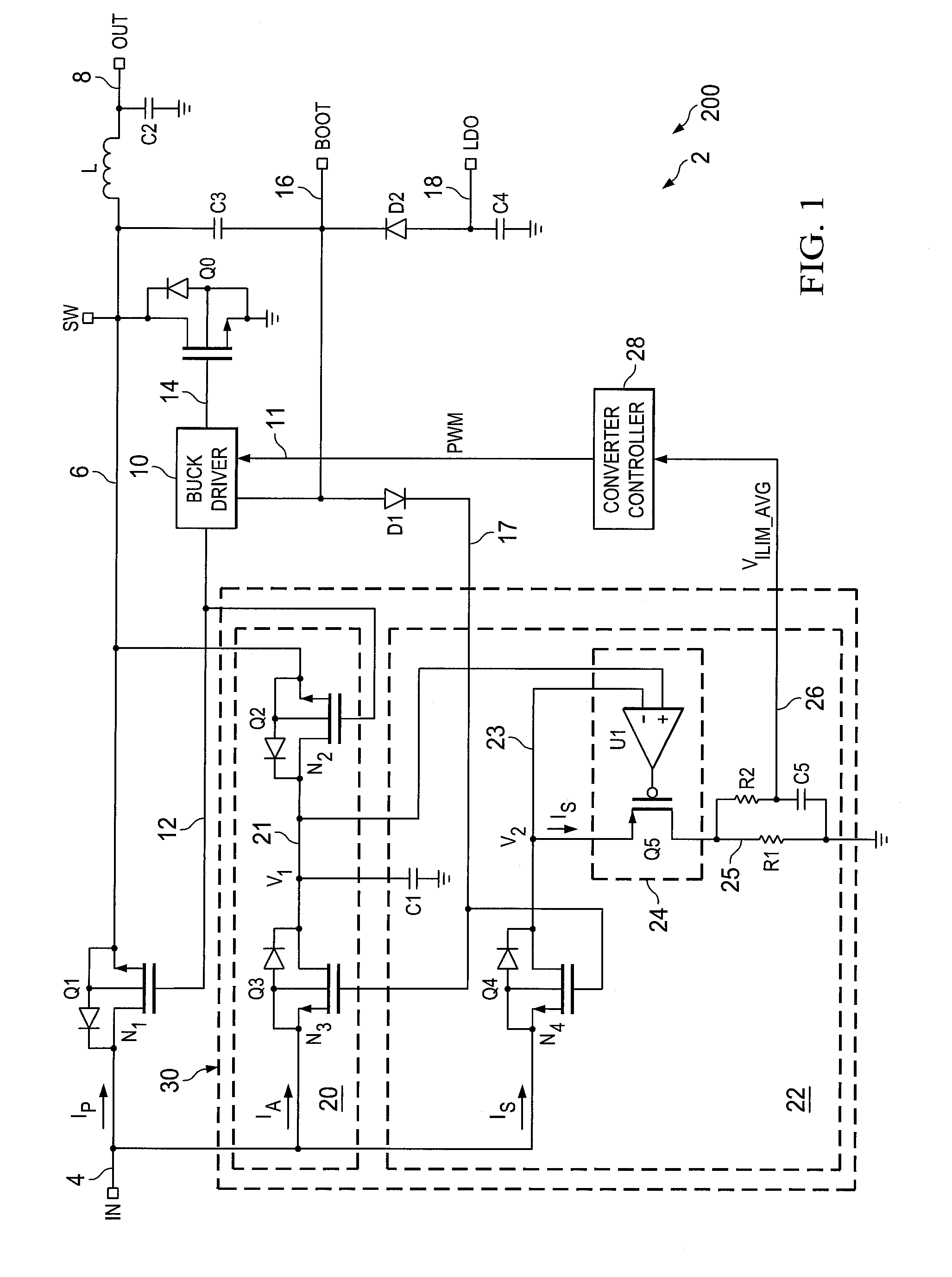
[0017]Referring initially to FIGS. 1-3, FIG. 1 shows an integrated circuit (IC) 200 including a switch mode buck converter 2 with an input current sensing apparatus 30 connected in parallel with a high-side power FET Q1. The converter 2 may be pa...


PUM


Abstract

Methods and apparatus are presented for sensing current flowing in a power transistor of a switch mode converter, in which a voltage is sensed across a first field effect transistor connected in a series circuit branch in parallel with the power transistor, and the sensed voltage is used to generate output signal to indicate the current flowing in the power transistor.

Description

FIELD OF THE INVENTION[0001]The present disclosure relates to power conversion circuitry, and more particularly to apparatus and methods for sensing switch mode power converter current without series sensing components.BACKGROUND OF THE INVENTION[0002]Power conversion circuitry is employed in many applications, such as in portable devices using external power from a universal serial bus (USB) connection to operate the device and / or to charge internal batteries. In many instances, the current drawn from a source may need to be limited, for example, according to specifications published for devices drawing power from a USB connection. For instance, portable devices are limited to drawing at most 100 mA from a USB 2.0 connection, unless a higher limit (e.g., up to 500 mA) is negotiated. Similarly, USB 3.0 connections are typically limited to drawing 150 mA unless a higher amount (e.g., up to 900 mA) is negotiated. Accordingly, power management circuitry in many portable devices provide...

Claims


Application Information

Patent Timeline
Patent Type & Authority Applications(United States)
IPC IPC(8): G01R19/00G05F1/10
CPCG05F1/10G01R19/00G01R19/0092H02M3/158H02M3/1582H02M3/156
Inventor HU, YONGXUANHOQUE, MOHAMMAD RASHEDUL
Owner TEXAS INSTR INC
Why Eureka
Try Eureka