Motor driving system

a technology of driving system and motor, which is applied in the direction of motor/generator/converter stopper, electronic commutator, dynamo-electric converter control, etc., can solve the problems of increasing costs, affecting the reliability of sensorless control algorithm, etc., to achieve the effect of small overall size, low manufacturing cost and guaranteed reliability

Active Publication Date: 2014-02-27
FUJI ELECTRIC CO LTD
View PDF7 Cites 15 Cited by
  • Summary
  • Abstract
  • Description
  • Claims
  • Application Information

AI Technical Summary

Benefits of technology

[0026]Preferably, a motor driving system without a magnetic pole position detecting means can be constructed, wherein reliability of the sensorless control algorithm has been guaranteed through normality determination by means of the motor driving system. This aspect of the invention provides a motor driving system with a small overall size, a low manufacturing cost, and a reduced failure rate. These characteristics are best fits to application to electric vehicles.
[0027]A motor driving system of the present invention certifies reliability of the sensorless control algorithm with the first abnormality determining means provided in the control device. A motor driving system equipped with a sensorless control algorithm that has been guaranteed reliable performs a smaller size, a lower price, and a reduced failure rate than a driving system having a magnetic pole position detecting means. A motor driving system of the invention also contributes to improving safety of an electric vehicle provided with such a driving system.

Problems solved by technology

In the conventional technology disclosed in Japanese Unexamined Patent Application Publication No. 2001-112282, although the information on the magnetic pole position is doubled improving reliability, the provision of the magnetic pole position detector, an abnormality detecting device, and the magnetic pole position estimating device enlarges the system and raises the costs.
As a consequence, if the sensorless control itself becomes unstable, the accuracy of magnetic pole position estimation deteriorates, which leads to erroneous determination of abnormality of the magnetic pole position detector, and even run-away of the motor may occur.
If the reliability of the sensorless control is not guaranteed, however, a driving system depending on the sensorless control cannot be employed without hesitation for such an application as electric vehicles that require absolute safety.

Method used


Image

  • Motor driving system
  • Motor driving system
  • Motor driving system

Examples


first embodiment

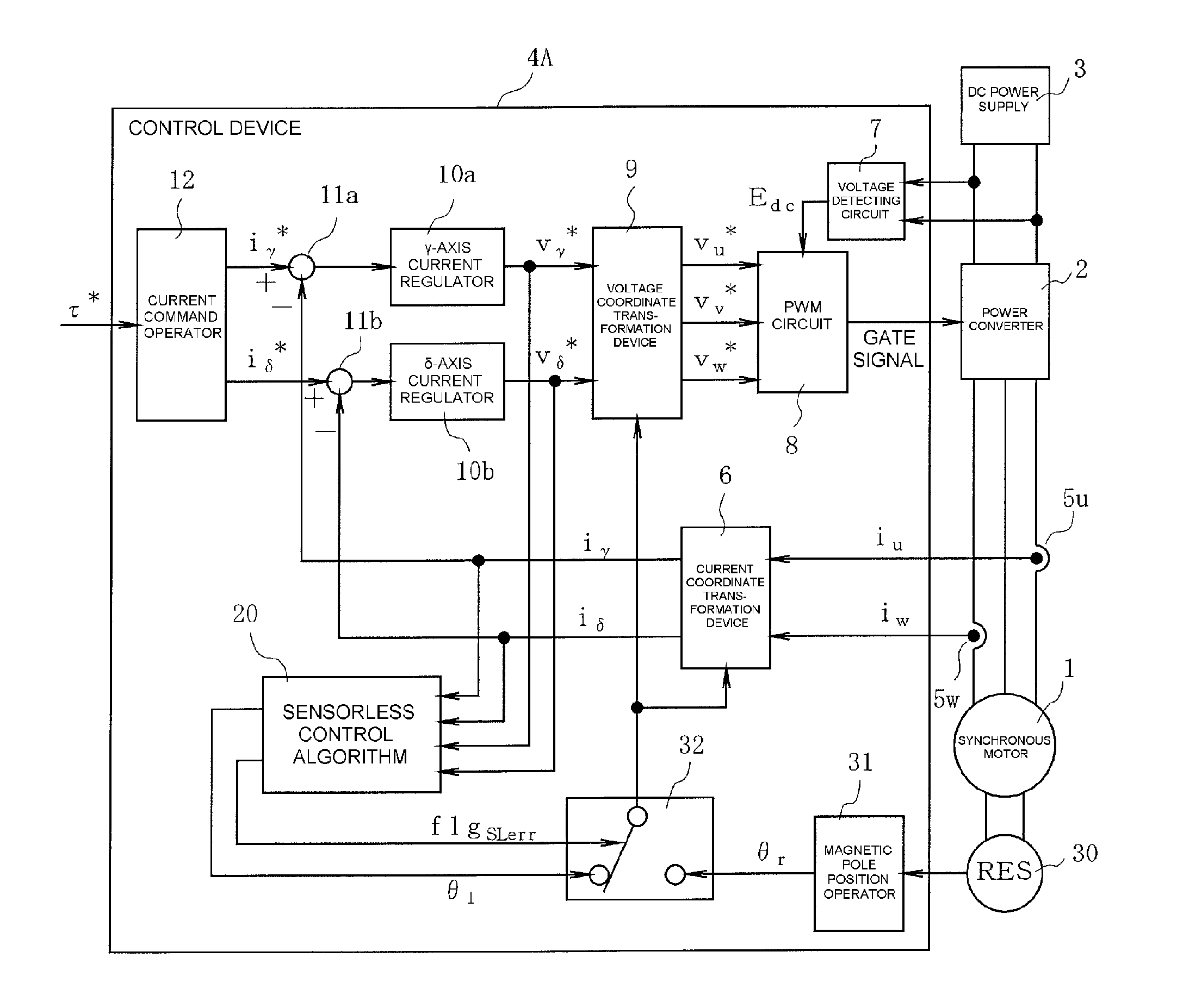
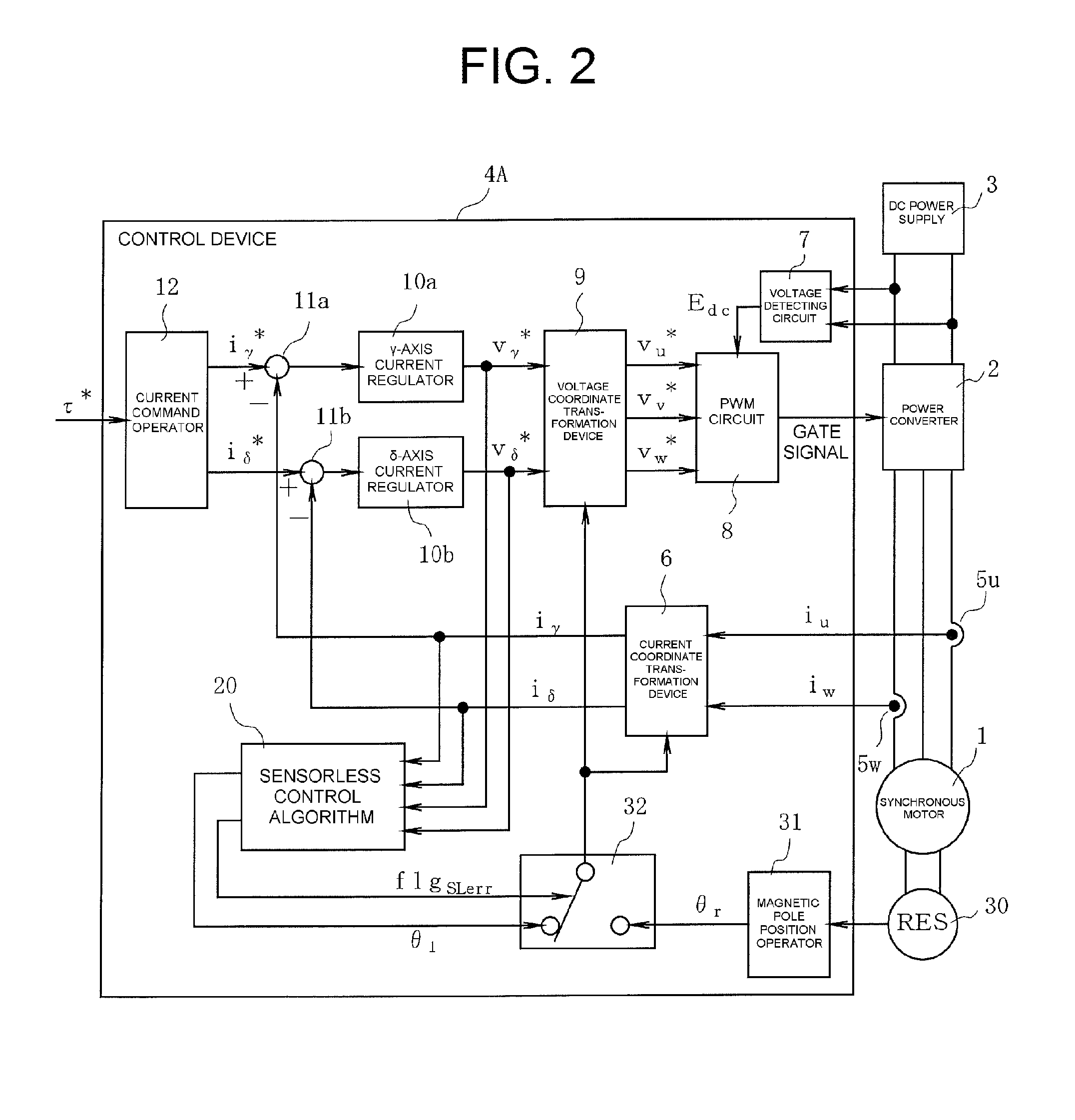
[0043]FIG. 2 shows a structure of a motor driving system according to the present invention. The motor driving system of FIG. 2 is composed of a main circuit and a control device 4A. The main circuit comprises a permanent magnet synchronous motor 1, a power converter 2 such as an inverter, a DC power supply 3, and a magnetic pole position detector 30 (a magnetic pole position detecting means) that is additionally provided to guarantee reliability of sensorless control. The control device 4A comprises a sensorless control algorithm device 20, which is a feature of the present invention.

[0044]The following describes the structure and operation of the control device 4A.

[0045]In the control device 4A in FIG. 2, a current command operator 12 executes operation of γ-axis and δ-axis current command values iγ* and iδ* for controlling an output torque of the motor 1 to a torque command value τ*. A u-phase current detector 5u and a w-phase current detector 5w deliver a u-phase current detecte...

second embodiment

[0064]FIG. 5 shows an example of structure of a motor driving system according to the present invention.

[0065]A control device 4B of the motor driving system according to the second embodiment has an alarm generator 40 added to the control device 4A shown in FIG. 2. The alarm generator 40 generates a first alarm alarm1 when the sensorless control algorithm device 20 becomes abnormal setting the flgSLerr to the value “1”. The alarm1 can be a warning sound or a warning light giving a caution to the operator.

[0066]Noticing the alarm, the operator recognizes that the sensorless control algorithm has become abnormal and that the magnetic pole position for use in the current coordinate transformation device 6 and the voltage coordinate transformation device 9 has changed over from the magnetic pole position estimated value θ1 to the magnetic pole position detected value θr. Thus, the operator can safely manually stop the motor driving system.

third embodiment

[0067]FIG. 6 shows an example of structure of a motor driving system according to the invention.

[0068]The control device 4C of the motor driving system according to the third embodiment has a data storage means 50 that is essentially composed of a memory. The date storage means 50 stores the input and output data of the sensorless control algorithm device 20, the data including θ1, vγ*, vδ*, iγ, and iδ in the example of FIG. 6, during a specified period of time around the occurrence of abnormality in the sensorless control algorithm corresponding to the value of the flag flgSLerr.

[0069]The data storage means 50, as shown in FIG. 7, comprises a ring buffer 52 that is composed using a memory 51 in a random access memory (RAM) or static RAM (SRAM) within a CPU and is capable of storing data during a certain period of time. The data storage means 50 also has a delay element 53.

[0070]In a normal state of the sensorless control algorithm device 20, in which flgSLerr=“0”, data are written ...


PUM


Abstract

A motor driving system is disclosed having a control device 4A for controlling a synchronous motor 1, the control device 4A comprising a sensorless control algorithm device 20 that includes an abnormality determining device 25 for determining abnormality of the algorithm based on a magnetic pole position error estimated value of the motor 1. When the abnormality determining device 25 has determined abnormality of the algorithm, the control device 4A controls a power converter 2 using a magnetic pole position detected value detected by a magnetic pole position detector 30 attached to the motor, in place of using a magnetic pole position estimated value. This motor driving system can guarantee reliability of the sensorless control algorithm device 20 while assuring safety. Safety of electric vehicles is enhanced by installing the motor driving system that has been guaranteed reliable.

Description

CROSS-REFERENCE TO RELATED APPLICATION[0001]This application is based on, and claims priority to, Japanese Patent Application No. 2012-185102, filed on Aug. 24, 2012, contents of which are incorporated herein by reference.BACKGROUND OF THE INVENTION[0002]1. Field of the Invention[0003]The present invention relates to a motor driving system that employs either an estimated value of a magnetic pole position or a detected value of a magnetic pole position corresponding to a normal or abnormal condition in sensorless control of the motor driving system. The invention also relates to an electric vehicle provided with such a motor driving system.[0004]2. Description of the Related Art[0005]In order to reduce a size and a cost of a driving system for a synchronous motor, a drive control method so-called sensorless control method has been proposed that does not employ a magnetic pole position detecting device to detect the magnetic pole position of a rotor.[0006]The sensorless control, as i...

Claims


Application Information

Patent Timeline
Patent Type & Authority Applications(United States)
IPC IPC(8): H02P23/00B60L3/00B60L9/18H02P6/06H02P6/08H02P6/12H02P6/18H02P6/182H02P6/28
CPCH02P6/16H02P23/0077H02P6/182H02P29/022H02P29/032
Inventor KURODA, TAKESHITOBA, AKIO
Owner FUJI ELECTRIC CO LTD
Why Eureka
Try Eureka