Variable capacitor

a variable capacitor and capacitor technology, applied in the field of variable capacitors, can solve the problems of increased power consumption, reduced service life, and inability to meet the needs of variable capacitors, and achieve the effect of high change ra

Inactive Publication Date: 2014-02-27
ALPS ALPINE CO LTD
View PDF2 Cites 6 Cited by
  • Summary
  • Abstract
  • Description
  • Claims
  • Application Information

AI Technical Summary

Benefits of technology

[0012]Preferably, the variable capacitor elements each include a dielectric deposited on at least one surface of the fixed electrode or the movable electrode. In the case where the variable capacitor elements each include the dielectric, since the use of the AC drive voltage allows creation of a moment at which charging of the dielectric is reset (to zero), the movable electrode can be prevented from being attached to the fixed electrode.
[0013]Preferably, a frequency of the drive voltage applied to the drive electrodes of the variable capacitor elements by the drive control unit is a resonant frequency of the movable electrode determined by the beam or a frequency different from the resonant frequency within a predetermined range. In this case, the effect of multiplication by the resonance of the movable electrode yields a large displacement of the movable electrode in low-voltage driving. Advantageously, a high change rate can be provided.

Problems solved by technology

Disadvantageously, this leads to increased power consumption.
Unfortunately, an apparatus is inevitably increased in size.
Since portable apparatuses are, however, always required to have small size and low profile, including such a variable capacitor is a disadvantage in terms of achieving small size and low profile.
Disadvantageously, the variable capacitor element may fail to function.
This causes ripple in the capacitance of the variable capacitor.
Unfortunately, such a capacitor is difficult to use as a circuit element.

Method used


Image

  • Variable capacitor
  • Variable capacitor
  • Variable capacitor

Examples


Embodiment Construction

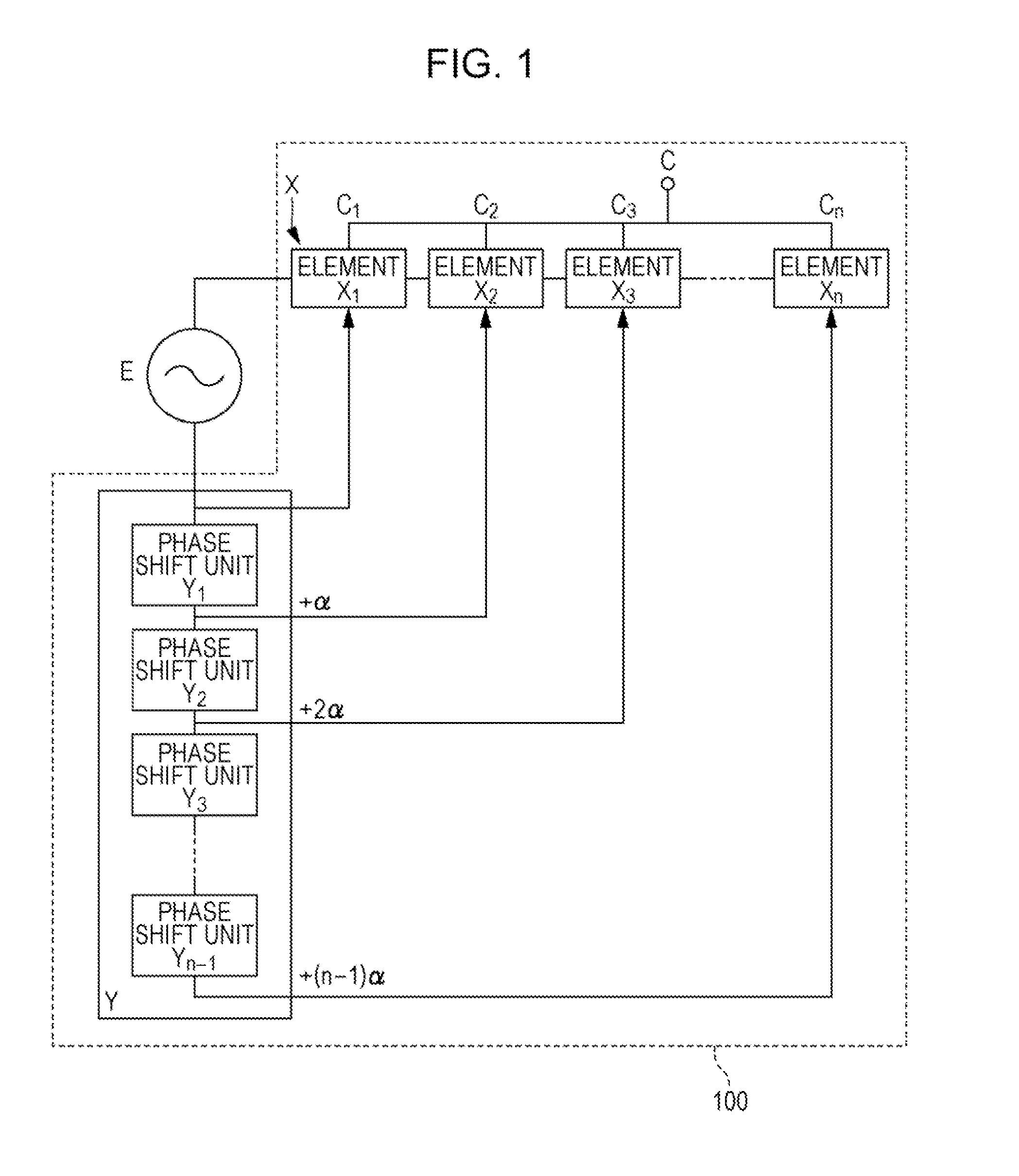
[0031]FIG. 1 is a schematic block diagram illustrating an entire configuration of a variable capacitor according to the present invention. A variable capacitor 100 includes a plurality of variable capacitor elements X (X1 to Xn; n is an integer) connected in parallel with one another and a multistage phase shifter Y. The multistage phase shifter Y is a drive control unit for the variable capacitor elements X1 to Xn and includes a plurality of phase shift units Y1 to Yn-1 to apply an AC drive voltage supplied from an external AC power supply E to the variable capacitor element X1, sequentially shift the drive voltage by a predetermined phase difference α, and apply the shifted drive voltages to the respective variable capacitor elements X2 to Xn.

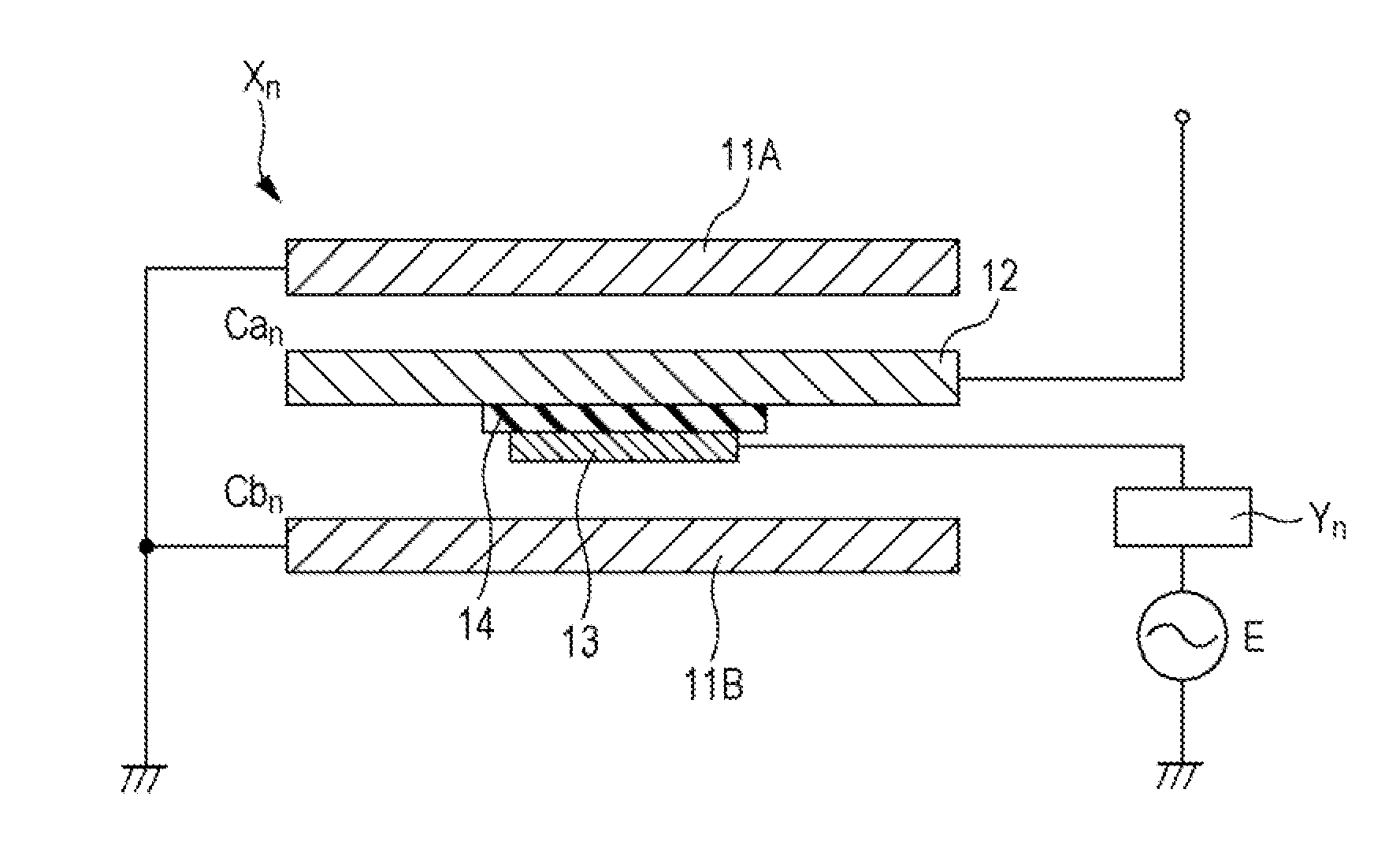
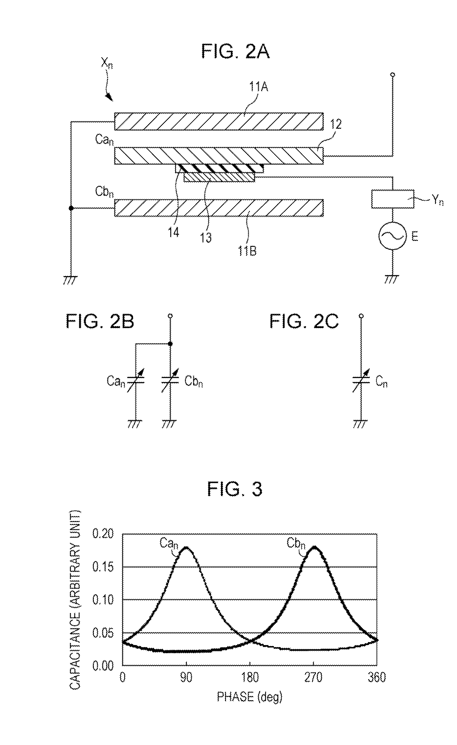
[0032]FIGS. 2A to 9 illustrate the variable capacitor element Xn according to a first embodiment. FIG. 2A is a schematic diagram illustrating, in outline, the configuration of the variable capacitor element Xn. FIG. 2B is a circuit diagram of...


PUM


Abstract

A variable capacitor includes a plurality of variable capacitor elements connected in parallel with one another, the variable capacitor elements each including a fixed electrode and a movable electrode facing each other, a beam supporting the movable electrode displaceably, and a drive electrode supplied with a drive voltage to change spacing between the fixed electrode and the movable electrode. The variable capacitor further includes a drive control unit configured to sequentially apply an AC drive voltage to the drive electrodes of the variable capacitor elements with a predetermined phase difference for each element. The sum of capacitances of the variable capacitor elements is an output capacitance.

Description

CLAIM OF PRIORITY[0001]This application is a Continuation of International Application No. PCT / JP2012 / 053256 filed on Feb. 13, 2012, which claims benefit of Japanese Patent Application No. 2011-124382 filed on Jun. 2, 2011. The entire contents of each application noted above are hereby incorporated by reference.BACKGROUND OF THE INVENTION[0002]1. Field of the Invention[0003]The present invention relates to a variable capacitor in which spacing between a fixed electrode and a movable electrode facing each other varies depending on voltage applied.[0004]2. Description of the Related Art[0005]A variable capacitor included in an oscillator circuit or a modulator circuit of, for example, a mobile phone, can change a capacitance so that the circuit yields a desired output. Such a capacitor has recently been achieved using microelectromechanical systems (MEMS) technology. Specifically, the MEMS variable capacitor includes a fixed electrode, a movable electrode facing the fixed electrode wi...

Claims


Application Information

Patent Timeline
Patent Type & Authority Applications(United States)
IPC IPC(8): H01G5/16
CPCH01G5/16H01G5/38H01G5/18B81B3/0056B81B2201/0221
Inventor MURATA, SHINJI
Owner ALPS ALPINE CO LTD
Why Eureka
Try Eureka