
Switched reluctance motor assembly

Inactive Publication Date: 2014-02-27
SAMSUNG ELECTRO MECHANICS CO LTD
View PDF18 Cites 6 Cited by
  • Summary
  • Abstract
  • Description
  • Claims
  • Application Information

AI Technical Summary

Benefits of technology

The present invention is a vacuum cleaner motor assembly that integrates a diffuser and a housing to simplify the structure and improve efficiency and reliability. The design features a stable support structure for the bearing part, which ensures better performance and operation of the motor.

Problems solved by technology

However, due to vibration or noise generated at the time of driving the switched reluctance motor (SRM) mounted in a vacuum cleaner module, operation performance of a product is deteriorated.
In addition, coupling force of two bearing parts coupled to upper and lower portions of a shaft are reduced, such that it is difficult to secure concentricity of the two bearing parts.
As a result, vibration and noise are generated due to the bearing parts at the time of an operation of the motor.

Method used


Image

  • Switched reluctance motor assembly
  • Switched reluctance motor assembly
  • Switched reluctance motor assembly

Examples


Embodiment Construction

[0022]The objects, features and advantages of the present invention will be more clearly understood from the following detailed description of the preferred embodiments taken in conjunction with the accompanying drawings. Throughout the accompanying drawings, the same reference numerals are used to designate the same or similar components, and redundant descriptions thereof are omitted. Further, in the following description, the terms “first”, “second”, “one side”, “the other side” and the like are used to differentiate a certain component from other components, but the configuration of such components should not be construed to be limited by the terms. Further, in the description of the present invention, when it is determined that the detailed description of the related art would obscure the gist of the present invention, the description thereof will be omitted.

[0023]Hereinafter, preferred embodiments of the present invention will be described in detail with reference to the attac...


PUM


Abstract

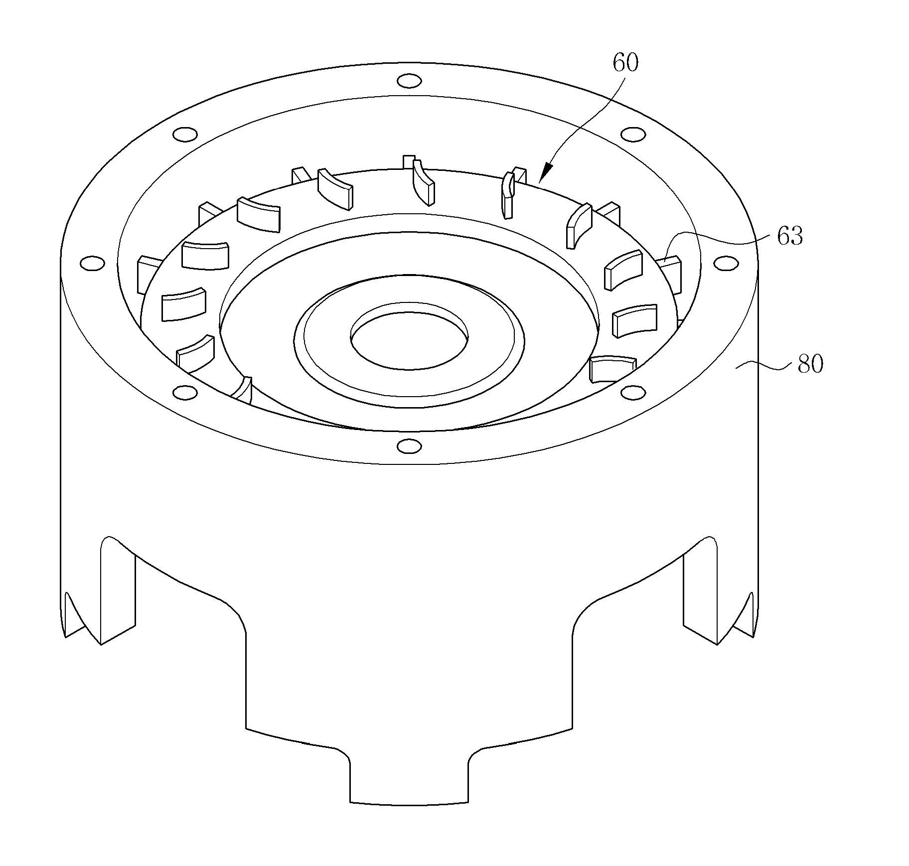
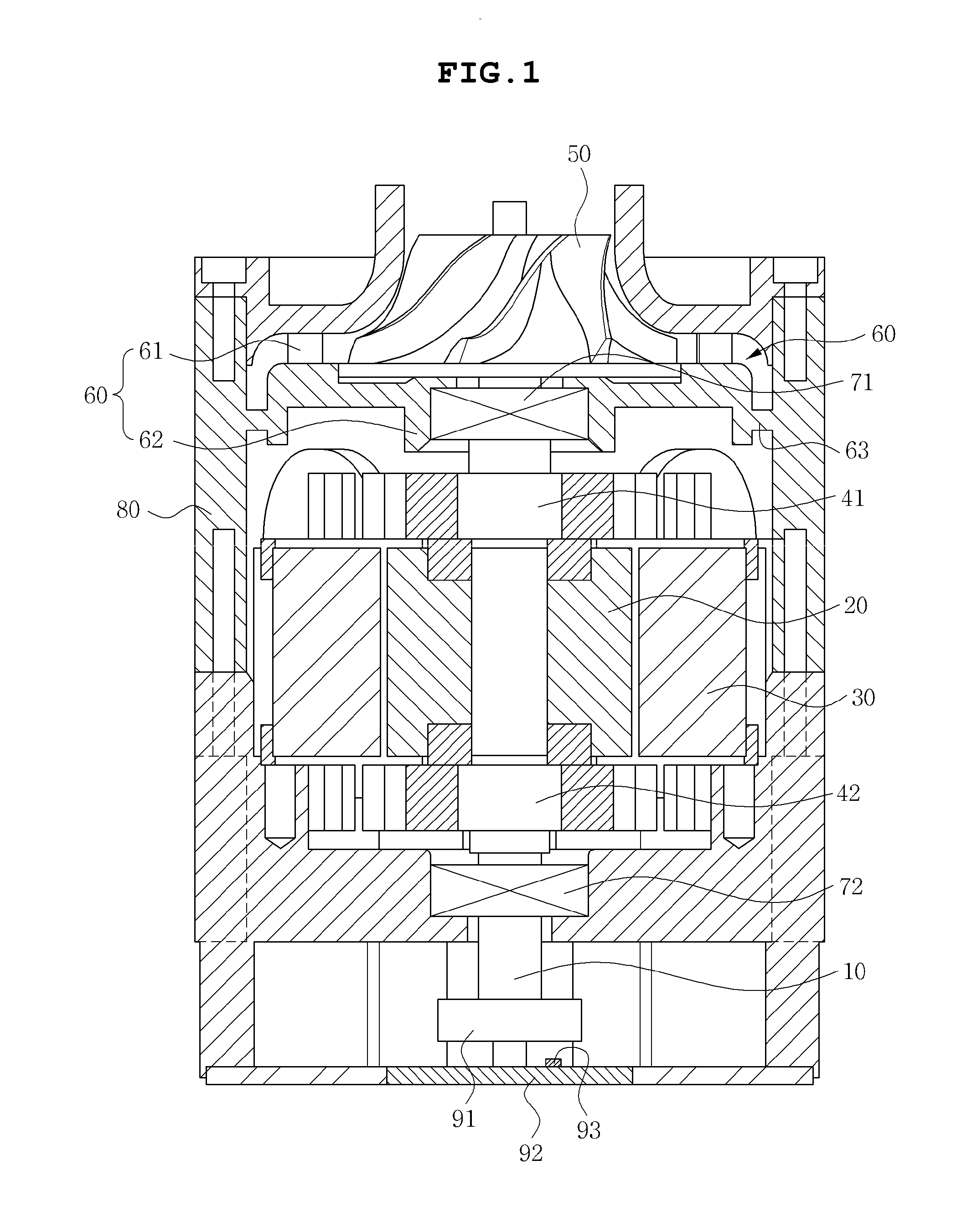
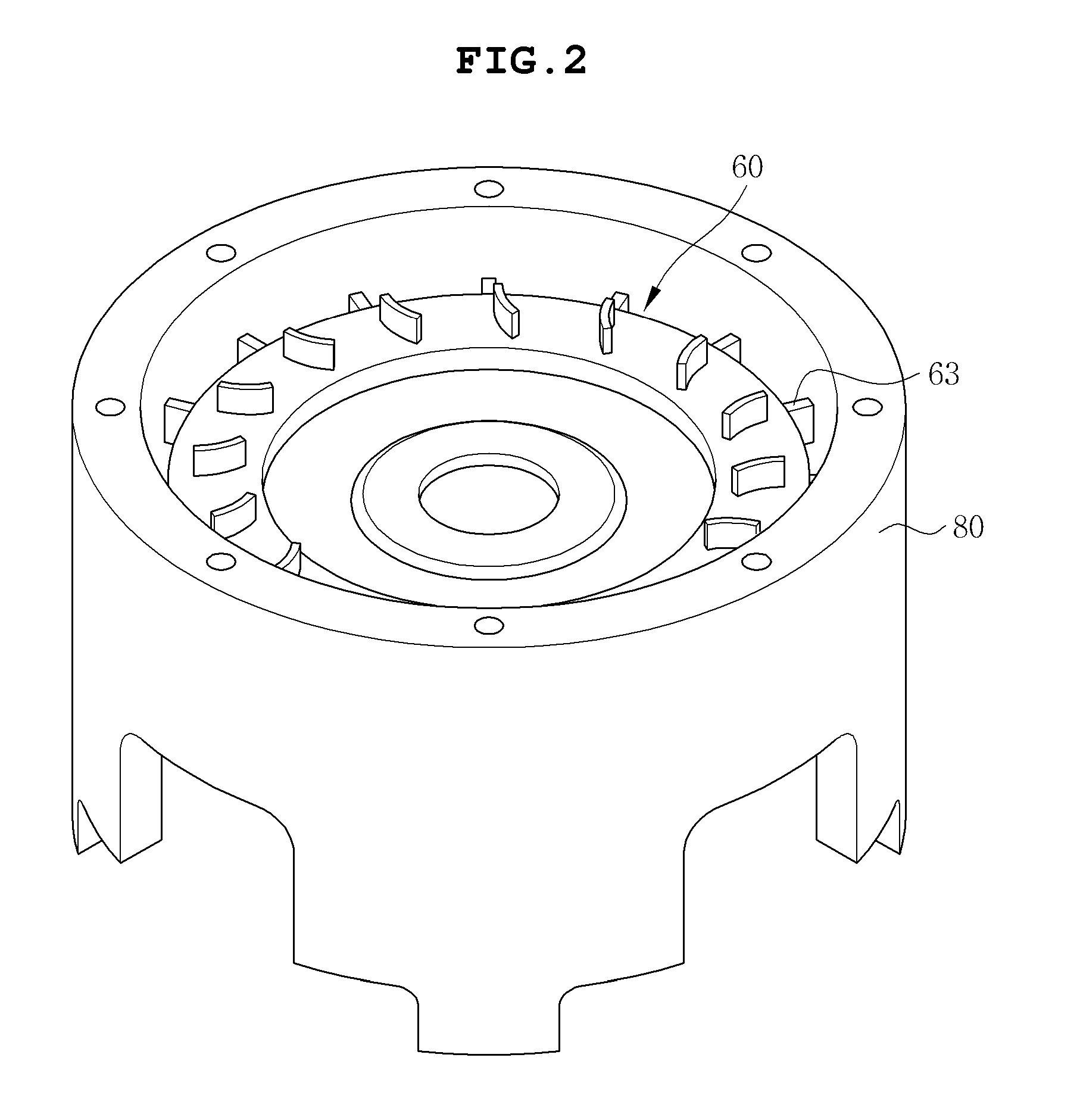
Disclosed herein is a switched reluctance motor assembly capable of reducing an assembling error that is generated according to separate assembling and improving precision of assembling of bearing parts by forming a diffuser part and a motor housing integrally with each other. In the switched reluctance motor assembly, the diffuser is coupled integrally with the housing, such that a separate member for fixing the diffuser is omitted, thereby making it possible to reduce vibration according to driving of a motor and noise according to the vibration.

Description

CROSS REFERENCE TO RELATED APPLICATION[0001]This application claims the benefit of Korean Patent Application No. 10-2012-0091814, filed on Aug. 22, 2012, entitled “Switched Reluctance Motor Assembly”, which is hereby incorporated by reference in its entirety into this application.BACKGROUND OF THE INVENTION[0002]1. Technical Field[0003]The present invention relates to a switched reluctance motor assembly.[0004]2. Description of the Related Art[0005]Generally, a switched reluctance motor (SRM) called an SR motor is a motor in which both of a stator and a rotor have a magnetic structure, which is a salient pole, the stator has a concentrated type coil wound therearound, and the rotor is configured only of an iron core without any type of excitation device (a winding or a permanent magnet), such that a competitive cost is excellent.[0006]More specifically, the switched reluctance motor (SRM), which rotates a rotor using a reluctance torque according to a change in magnetic reluctance, ...

Claims


Application Information

Patent Timeline
IPC IPC(8): F04D25/06
CPCF04D25/0606F04D25/06F04D29/4206F04D29/444F05D2250/52
Inventor YIM, JUNG KYUCHO, YONG WANSEO, SANG HOOH, MYUNG GEUNJUNG, SUNG TAI
Owner SAMSUNG ELECTRO MECHANICS CO LTD
Learn More