Purge method of canister in ffv, and purge mechanism of canister in ffv using the method

Active Publication Date: 2014-02-27
TOYOTA JIDOSHA KK
View PDF6 Cites 0 Cited by
  • Summary
  • Abstract
  • Description
  • Claims
  • Application Information

AI Technical Summary

Benefits of technology

[0045]In accordance with the present invention, even if the change of remaining amount of fuel vapor in a canister accompanying the change of the ratio of an alcohol component in alcohol blended fuel and/or an uneven concentration distribution of an alcohol component within a canister occur, in an FFV on which an internal-combustion engine using alcohol blended fuel is mounted, the desorption rate (the amoun

Problems solved by technology

Moreover, the surface of the fuel in the fuel tank tends to change due to a shake and vibration while a vehicle is moving.
For this reason, when the ratio of an alcohol component in alcohol blended fuel is changed, by using alcohol blended fuel with a different ratio of an alcohol component, or as the ratio of an alcohol component falls by evaporation in prolonged storage, etc., the quantity of the fuel vapor which desorbs from adsorption material at the time of a purge processing of a canister changes and it becomes difficult to estimate correctly the quantity of the fuel vapor introduced into an intake system.
As a result, an uneven concentration distribution of the alcohol component within the canister will arise, and the concentration as the whole fuel vapor and/or the ratio of the alcohol component which are contained in purge gas will change with advance of the purge processing.
As a result, since the desorption rate (the amount of desorption) as the whole fuel vapor at the time of a purge processing of the canister als

Method used

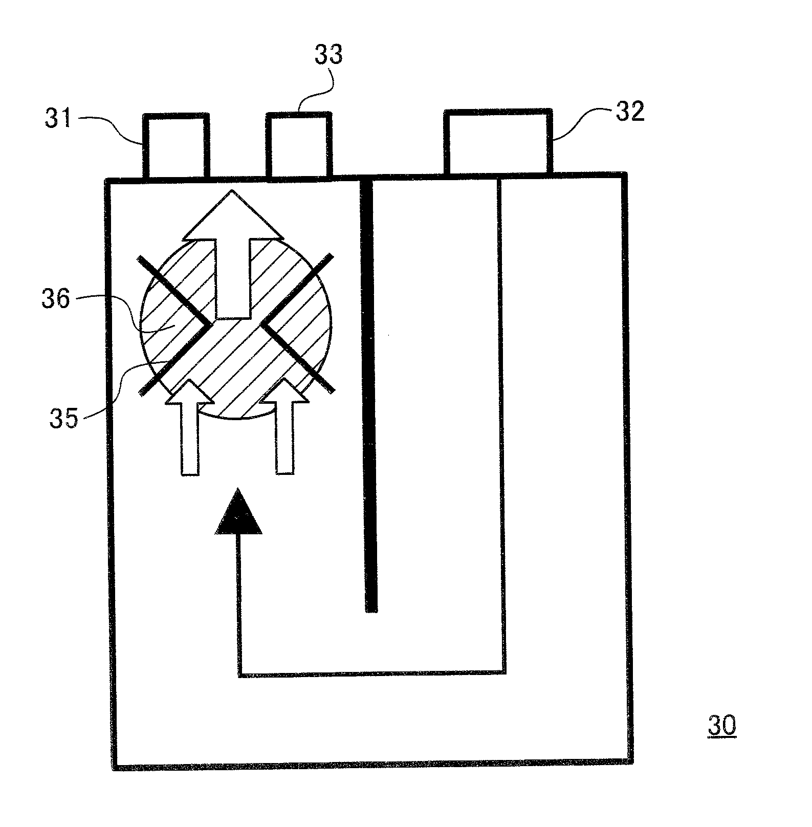
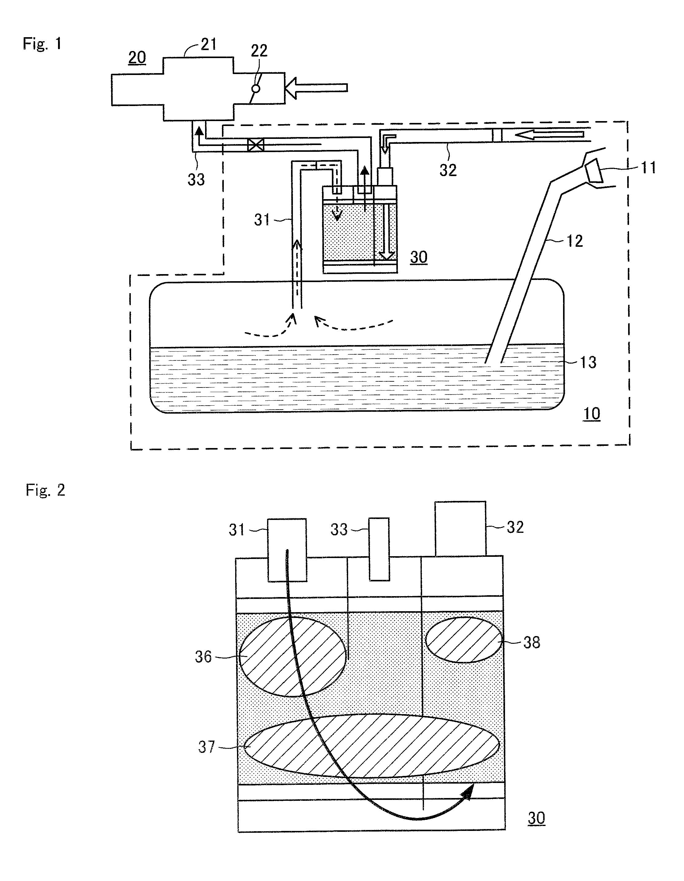
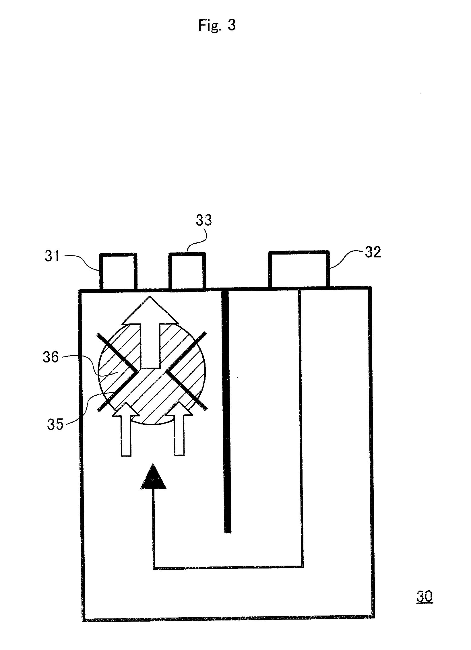

Image

  • Purge method of canister in ffv, and purge mechanism of canister in ffv using the method
  • Purge method of canister in ffv, and purge mechanism of canister in ffv using the method
  • Purge method of canister in ffv, and purge mechanism of canister in ffv using the method

Examples


example

[0202]As mentioned above, FIG. 8 is a flow chart showing the flow of a series of processing performed in a purge method of a canister in an FFV according to one embodiment of the present invention. Hereafter, the execution procedure of a purge method of a canister in an FFV according to one embodiment of the present invention will be explained in detail referring to the flow chart. In addition, a series of processing shown in the flow chart can be performed by an electrical control unit (not shown), for example, as an interruption processing for every predetermined crank angle.

[0203]As shown in FIG. 8, in the present embodiment, the alcohol concentration R-OH in the alcohol blended fuel stored in a fuel tank is acquired by an alcohol concentration detection means. Moreover, in the present embodiment, the temperature Tf of the alcohol blended fuel stored in the fuel tank is also acquired by detection means, such as a temperature sensor, etc. (Step S1). Next, based on the acquired alc...


PUM


Abstract

In an FFV (flexible fuel vehicle) on which an internal-combustion engine using alcohol blended fuel in mounted, the remaining amount of fuel vapor presumed to remain in a canister in accordance with a usual purge processing is presumed based on an alcohol concentration in the alcohol blended fuel. According to this remaining amount, the size of the tank side channel which is a channel in a canister near the connection section with a connection pathway (tank line) with a fuel tank is adjusted by a canister throttle control means, and/or, the timing of opening and closing of an intake valve is changed by a variable valve timing mechanism. Thereby, the desorption rate (the amount of desorption) of fuel vapor from adsorption material in a canister is adjusted, and the concentration of the fuel included in purge gas is adjusted. As a result, even when the change of the remaining amount of the fuel vapor adsorbed by the adsorption material in the canister and/or the uneven concentration distribution of an alcohol component within the canister occur, the accuracy of an air/fuel ratio control in the FFV can be raised, and the discharge of a toxic substance can be suppressed effectively.

Description

TECHNICAL FIELD[0001]The present invention relates to a method for promoting purge according to increase of the remaining amount of fuel vapor in a canister accompanying increase of the ratio of alcohol component in alcohol blended fuel in an FFV (Flexible Fuel Vehicle). Moreover, the present invention relates also to a purge mechanism of a canister in an FFV using the method.BACKGROUND ART[0002]Generally, a fuel tank of a vehicle with an internal-combustion engine as a driving source is disposed near an exhaust pipe in many cases and, for this reason, the fuel tank is heated by the heat from the exhaust pipe, etc. Moreover, the surface of the fuel in the fuel tank tends to change due to a shake and vibration while a vehicle is moving. From such a situation, an evaporative emission of fuel (henceforth, may be referred to as “fuel vapor”) is likely to be generated in a fuel tank. For this reason, a passage communicated with the external world, the (henceforth, may be referred to as a...

Claims


Application Information

Patent Timeline
IPC IPC(8): F02M25/08
CPCF02M25/08F02D13/0234F02D19/084F02M25/0854F02M25/089F02D41/0025Y02T10/12Y02T10/30
Inventor TSUKAGOSHI, TAKAHIROMORITA, KOUJIMATSUDA, KAZUHISA
Owner TOYOTA JIDOSHA KK
Why Eureka
Try Eureka