
Imaging member for offset printing applications

Inactive Publication Date: 2014-03-06
XEROX CORP
View PDF2 Cites 22 Cited by
  • Summary
  • Abstract
  • Description
  • Claims
  • Application Information

AI Technical Summary

Benefits of technology

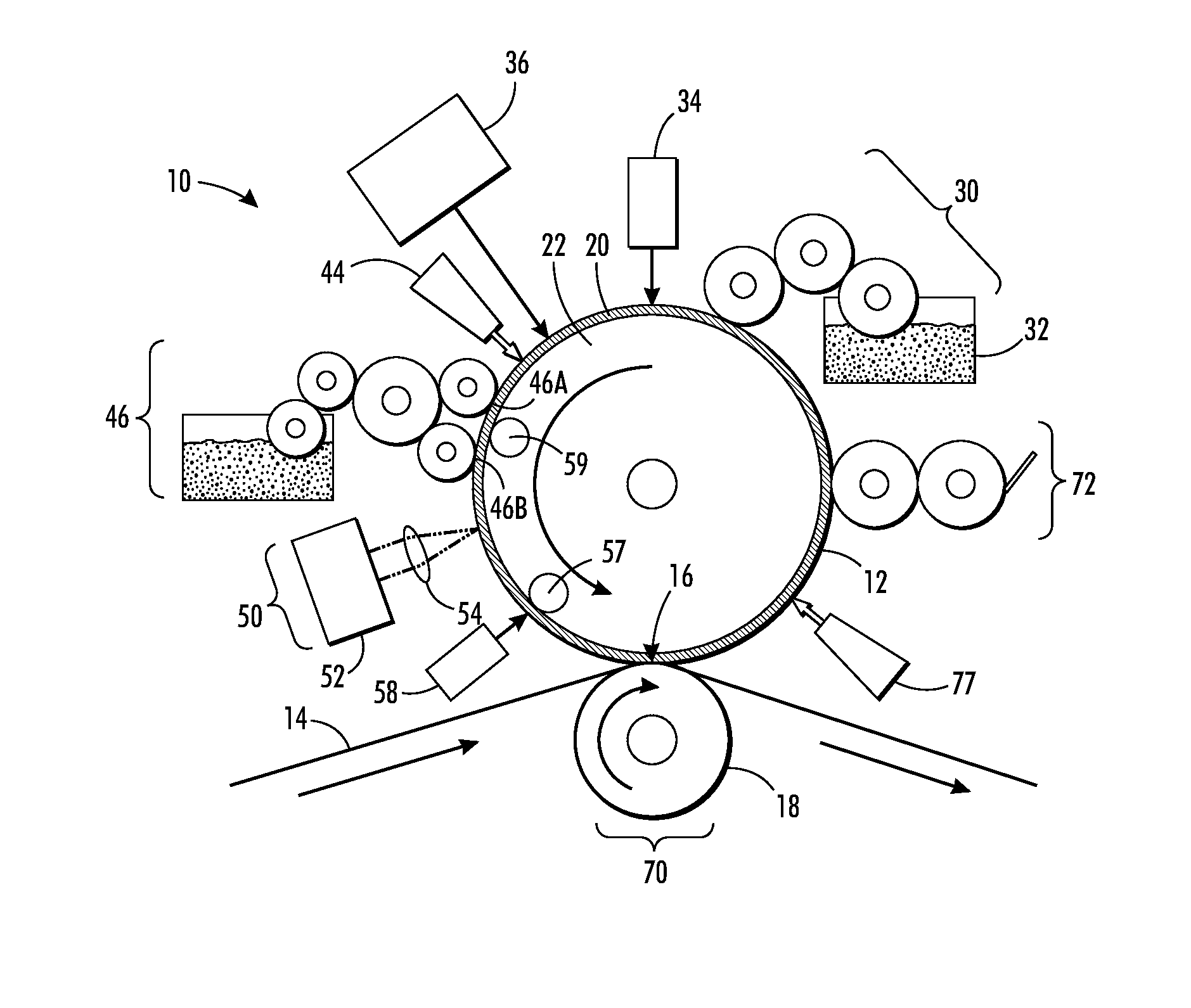
This patent is about imaging members for digital offset printing applications. The members have a surface layer made of silicone rubber and infrared-absorbing filler, which helps to improve the image quality of the printing process. The silicone rubber is present in a specific amount and the filler is present in a certain amount and has a specific size. The imaging member surface layer is deposited onto a mold and then cured. The filler used in the composition can be iron oxide, graphene, graphite, or carbon nanotubes. The thickness of the surface layer is about 0.5 to 4 millimeters. The process includes applying a fountain solution to the surface, forming a latent image, and transferring the image onto a substrate. The use of this surface layer improves the image quality and resolution of the printing process.

Problems solved by technology

However, they do not permit creating and printing a new pattern from one page to the next without removing and replacing the print cylinder and / or the imaging plate (i.e., the technique cannot accommodate true high speed variable data printing wherein the image changes from impression to impression, for example, as in the case of digital printing systems).
Furthermore, the cost of the permanently patterned imaging plates or cylinders is amortized over the number of copies.

Method used


Image

  • Imaging member for offset printing applications
  • Imaging member for offset printing applications
  • Imaging member for offset printing applications

Examples


example 1

[0095]RT 622 (commercially available from Wacker) is a two component silicone rubber that vulcanizes at room temperature. Part A comprises polydimethylsiloxane with functional groups. Part B comprises polydimethylsiloxane with functional groups and a platinum catalyst. The platinum catalyst serves as a curative agent for the silicone.

[0096]RT 622 was loaded into a ball milling jar with black iron oxide particles, a solvent, and a ball milling media. The material was tumble milled for a period of from 14 to 16 hours. The material was removed and a catalyst and an inhibitor were added. The material contained 10 wt % of black iron oxide (FeO). The material was then casted onto a textured Agfa mold (i.e. poured into a stationary mold) to form the imaging member plate. The imaging member plate had a smooth side and a rough side (i.e. microtextured).

[0097]As a Comparative Example, a corresponding plate was made using a silicone available from Toray. This plate contained 10 wt % of carbon ...

example 2

[0109]An RT 622 plate was produced via solution coating instead of casting, as in Example 1. Solution coating was carried out using a 12 inch by 36 inch Agfa plate. Solution coating was carried out by depositing the solution from a pumping system onto a rotating cylindrical surface.

[0110]The plate produced by casting (Example 1) was then compared to the plate produced by solution coating (Example 2). The results are shown in Table 3.

TABLE 3CA of theCA of therough sideImagingReleasingrough side(NovecplateFillerlayer(DI)7600)Example 110% FeONone126.1 (2.1)3.6 (1.2)Example 210% FeONone124.8 (2.6)5.1 (1.8)

[0111]The contact angles were roughly the same, indicating that the fabrication method did not affect the properties of the resulting surface layer.

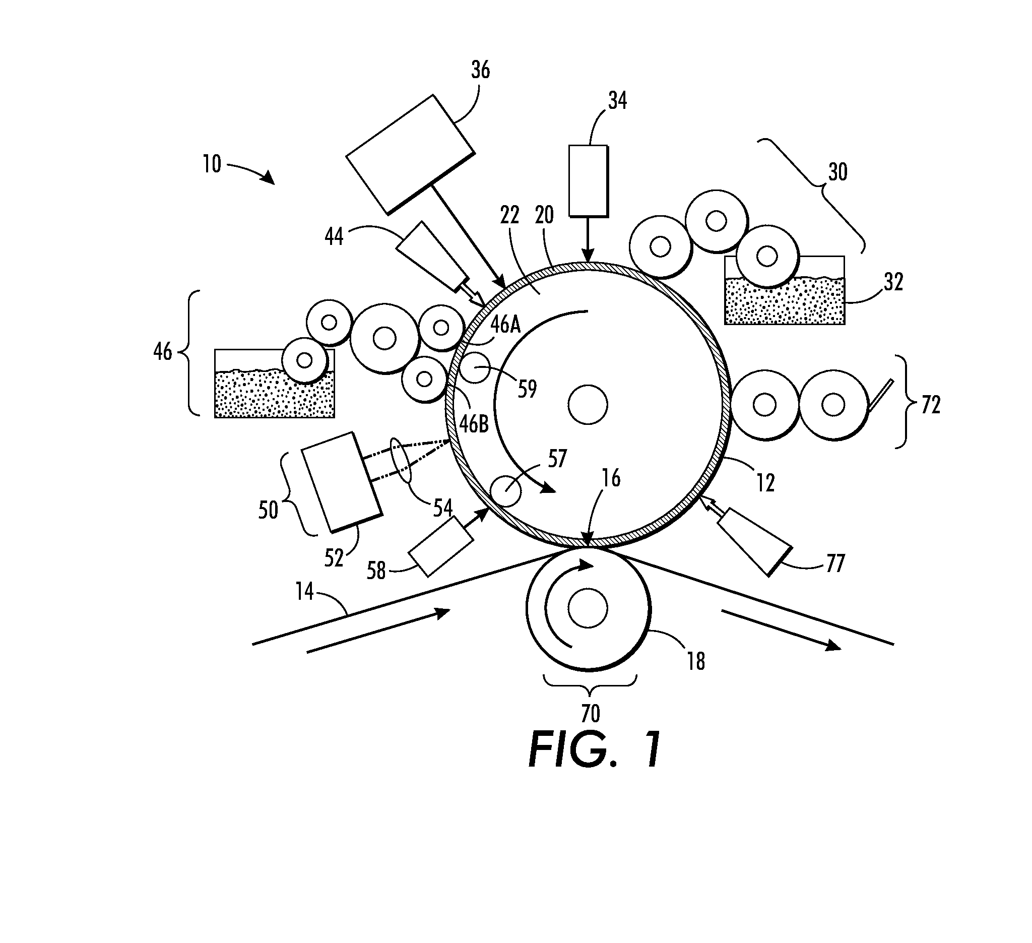
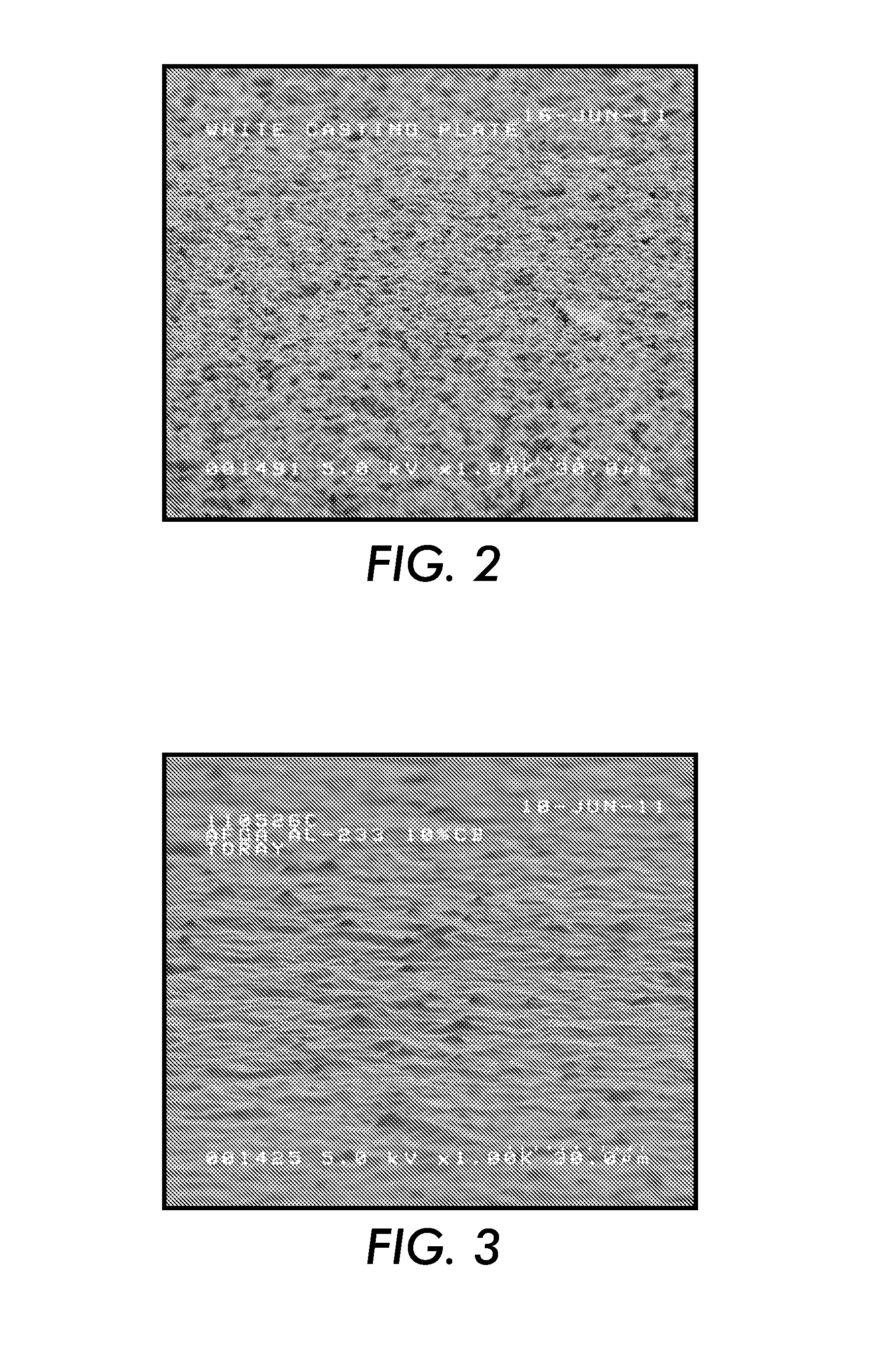
[0112]FIG. 9 is a SEM of the surface of the cast plate (Example 1). FIG. 10 is a SEM of the surface of the solution coated plate (Example 2). The plates of both examples exhibited good performance.


PUM

PropertyMeasurementUnit
Percent by massaaaaaaaaaa
Thicknessaaaaaaaaaa

Abstract

An imaging member includes a surface layer comprising a silicone rubber and an infrared-absorbing filler. Methods of fabricating the imaging member and processes for variable lithographic printing using the imaging member are also disclosed.

Description

[0001]The disclosure is related to U.S. patent application Ser. No. 13 / 095,714, filed on Apr. 27, 2011, titled “Variable Data Lithography System,” the disclosure of which is incorporated herein by reference in its entirety. The disclosure is related to co-pending U.S. patent application (Attorney Docket No. 056-0513), filed on the same day as the present disclosure, titled “Imaging Member for Offset Printing Applications,” the disclosure of which is incorporated herein by reference in its entirety; co-pending U.S. patent application (Attorney Docket No. 056-0512), filed on the same day as the present disclosure, titled “Imaging Member for Offset Printing Applications,” the disclosure of which is incorporated herein by reference in its entirety; co-pending U.S. patent application (Attorney Docket No. 056-0511), filed on the same day as the present disclosure, titled “Imaging Member for Offset Printing Applications,” the disclosure of which is incorporated herein by reference in its e...

Claims


Application Information

Patent Timeline
IPC IPC(8): B41F7/00G02B5/22B28B1/14
CPCB41F7/00
Inventor KELLY, MATTHEW M.GERVASI, DAVID J.KANUNGO, MANDAKINIHOWE, PATRICK J.ORNATSKA, MARYNABADESHA, SANTOKH S.
Owner XEROX CORP
Learn More