Systems and methods for generating power in a vehicle

a technology of electrical power generation and vehicle, which is applied in the direction of locomotives, battery/cell propulsion, transportation and packaging, etc., can solve the problems of increasing the overall cost and weight the increase of the fuel consumption of the cooling system of the rail vehicle, so as to achieve the effect of light weight and compactness

a technology of electrical power generation and vehicle, which is applied in the direction of locomotives, battery/cell propulsion, transportation and packaging, etc., can solve the problems of increasing the overall cost and weight the increase of the fuel consumption of the cooling system of the rail vehicle, so as to achieve the effect of light weight and compactness

US20140060378A1Active Publication Date: 2014-03-06GE GLOBAL SOURCING LLC

Image

  • Systems and methods for generating power in a vehicle
  • Systems and methods for generating power in a vehicle
  • Systems and methods for generating power in a vehicle

Examples


Embodiment Construction

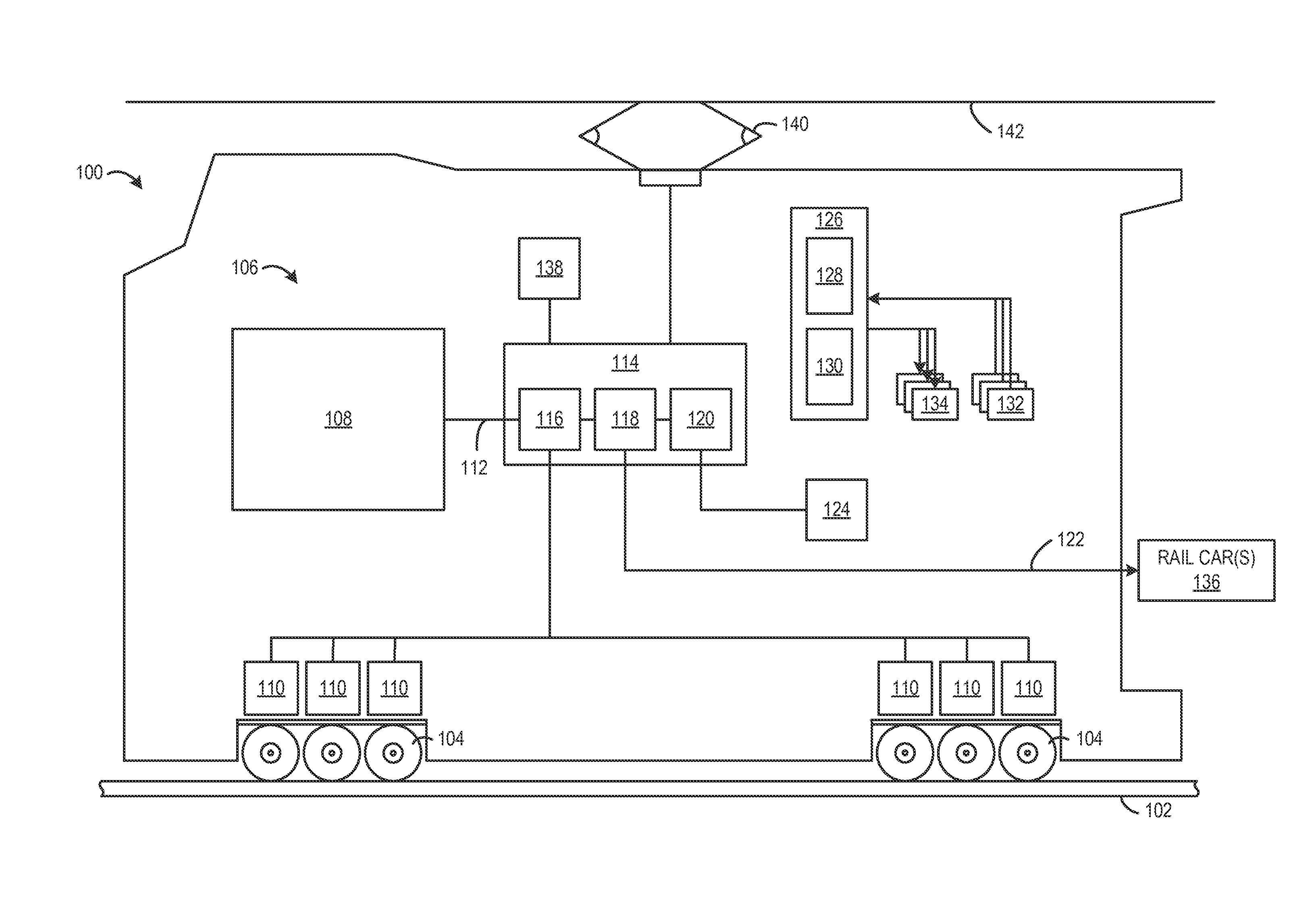
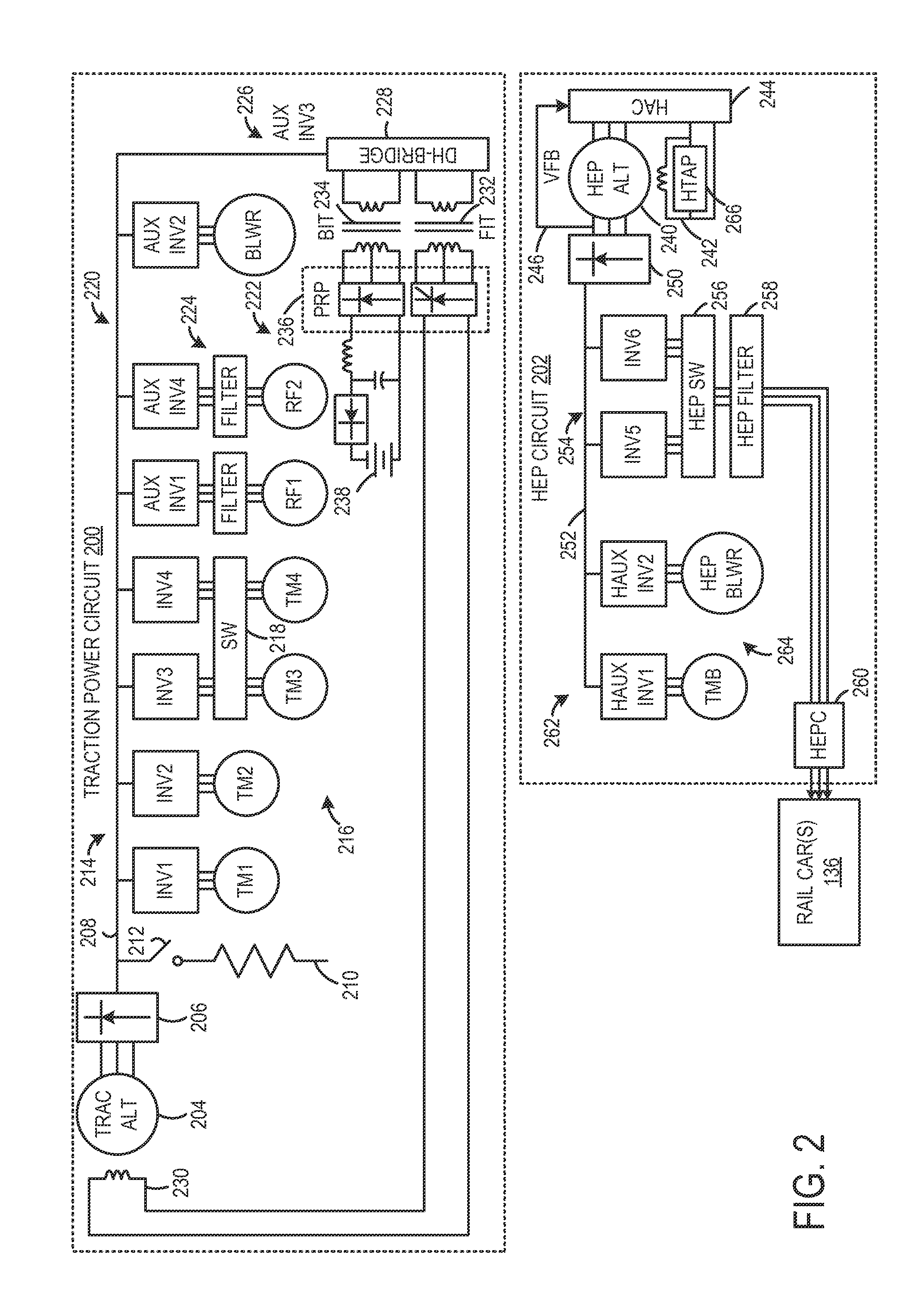
[0012]A train or other rail vehicle consist may include a plurality of rail vehicles interconnected with one another. (Generally, a consist is a group of vehicles that are mechanically linked to travel together along a route.) In some examples, one rail vehicle may generate electrical power and transmit the electrical power to other rail vehicles in the train. The present description relates to various embodiments of systems and methods for generating such electrical power in a rail vehicle. More particularly, the present description relates to a head-end-power or hotel-electric-power (HEP) alternator in a rail vehicle that is self-excited by a field winding positioned in the HEP alternator to provide electrical power to one or more other rail vehicles (such as rail cars) of a train or other rail vehicle consist. As used herein, a HEP alternator refers to an alternator that generates electrical power in a first rail vehicle that is transmitted to, and consumed by, electrical loads p...


PUM


Abstract

Various systems and method for generating electrical power in a rail vehicle are provided. In one embodiment, a vehicle system includes an electrical power generation unit operatively coupled with a drive shaft of an engine. The electrical power generation unit includes a fraction alternator and a head-end-power (HEP) alternator. The traction alternator is excited by power electronics positioned external to the traction alternator. The HEP alternator is self-excited by an exciter winding positioned in the HEP alternator.

Description

FIELD[0001]Embodiments of the subject matter disclosed herein relate to systems and methods for generating electrical power in a vehicle.BACKGROUND[0002]In some trains, electrical power may be generated at one vehicle in the train and distributed to other vehicles of the train. For example, a locomotive or a generator car may include an alternator, referred to as a head-end-power (HEP) alternator, that distributes electrical power to other cars in the train. In a passenger train for example, the electrical power generated by a HEP alternator may be distributed to passenger cars for lighting, electrical, and other hotel needs of passengers. In one example, a HEP alternator in a rail vehicle is excited by power electronics (e.g., including a battery, permanent magnets, driver circuits) that are externally positioned from the HEP alternator in the rail vehicle.[0003]In some cases, the external power electronics that provide excitation to the HEP alternator add additional overhead to a ...

Claims


Application Information

Patent Timeline
06 Mar 2014
Publication
US20140060378A1
IPC
B61C7/00; B60L50/10
CPC
B60L15/007; B60L2200/26; Y02T10/70; B60L50/53; B60L50/10; Y02T10/64; Y02T10/7072
Inventors
DAIGLE, JEFFREY; WORDEN, BRET DWAYNE