
Electrostatic chuck with radiative heating

a technology of radiative heating and electric chuck, which is applied in the direction of ohmic-resistance heating, electrostatic holding devices, electrical apparatus, etc., can solve the problems of insufficient typical post-implant annealing to restore all the damage caused, inability to accurately heat the workpiece, and crystal defects and amorphization

Active Publication Date: 2014-03-06
VARIAN SEMICON EQUIP ASSOC INC
View PDF5 Cites 11 Cited by
  • Summary
  • Abstract
  • Description
  • Claims
  • Application Information

AI Technical Summary

Benefits of technology

The present patent introduces a new type of electrostatic chuck that is optically transparent to infrared radiation. This allows for better heating of a semiconductor wafer during a process. The chuck has a mesh pattern or a transparent conductive film that ensures sufficient heating of the wafer while still allowing infrared radiation to pass through. The chuck can be used in conjunction with a reflector plate and a radiative heat source to focus more radiation on specific areas of the wafer. The technical effects of this invention include improved heating efficiency, better temperature control and better wafer quality during semiconductor manufacturing processes.

Problems solved by technology

Ion implantation involves the collision of energetic ions with atoms in the workpiece, which may result in crystal defects and amorphization.
However, for certain high dose implants and device structures, typical post-implant annealing may not be sufficient to restore all the damage caused by the implantation.
These methods may suffer from drawbacks, such as the inability to accurately heat the workpiece, or the ability to quickly and precisely adjust the temperature of the workpiece.
However, the ion implantation being performed on the upper surface of the workpiece may impart heat to the workpiece in a non-uniform manner.
In this case, the added heat applied to the lower surface of the workpiece cannot compensate for this non-uniformity and therefore, the workpiece cannot be held at a uniform temperature.
As the chuck has a thermal mass, which may be significant, rapid changes in applied heat cannot be achieved.

Method used


Image

  • Electrostatic chuck with radiative heating
  • Electrostatic chuck with radiative heating
  • Electrostatic chuck with radiative heating

Examples


Embodiment Construction

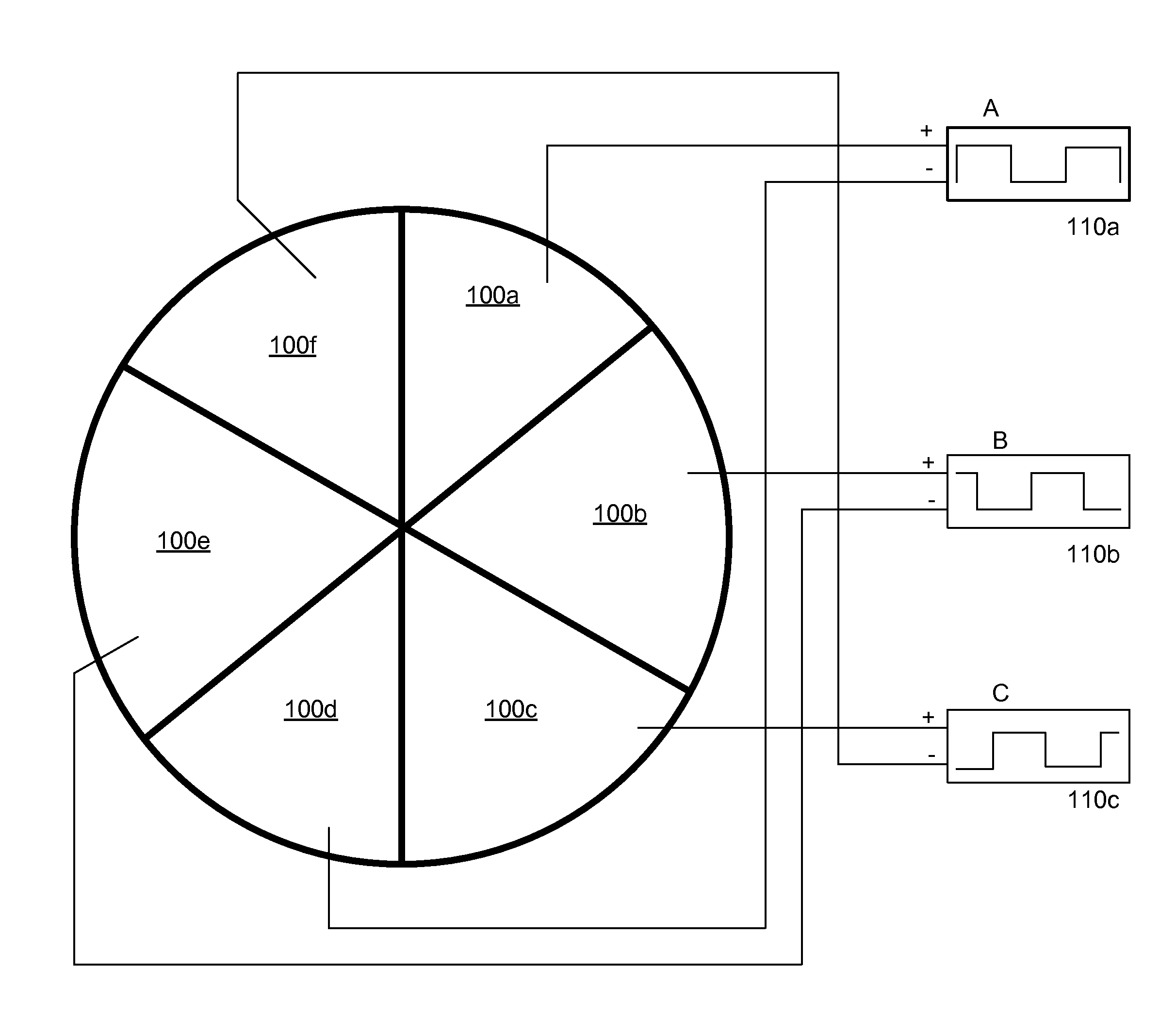
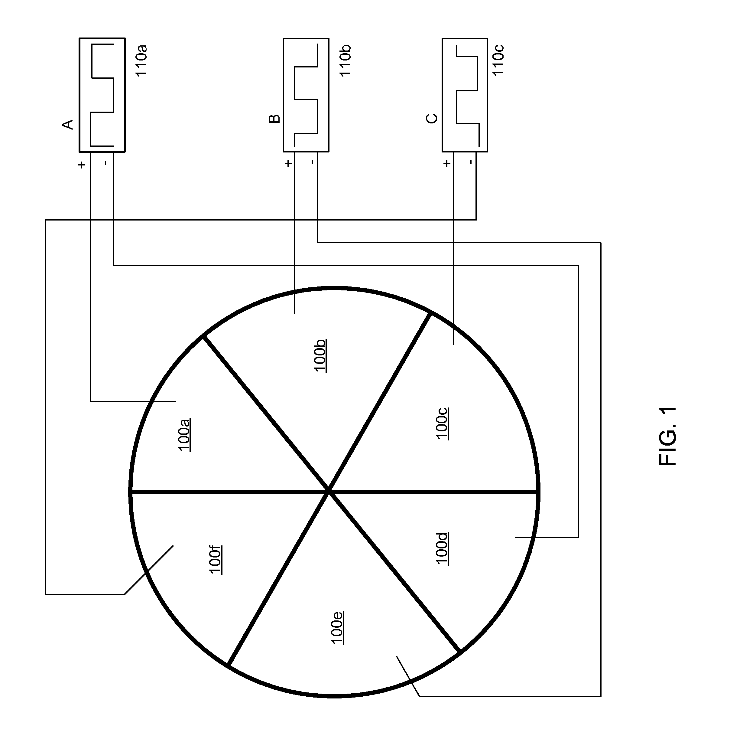
[0023]As described above, electrostatic chucks (ESCs) typically include several parts including a dielectric top layer, an insulating layer and a plurality of electrodes disposed between these layers or embedded in one of the layers.

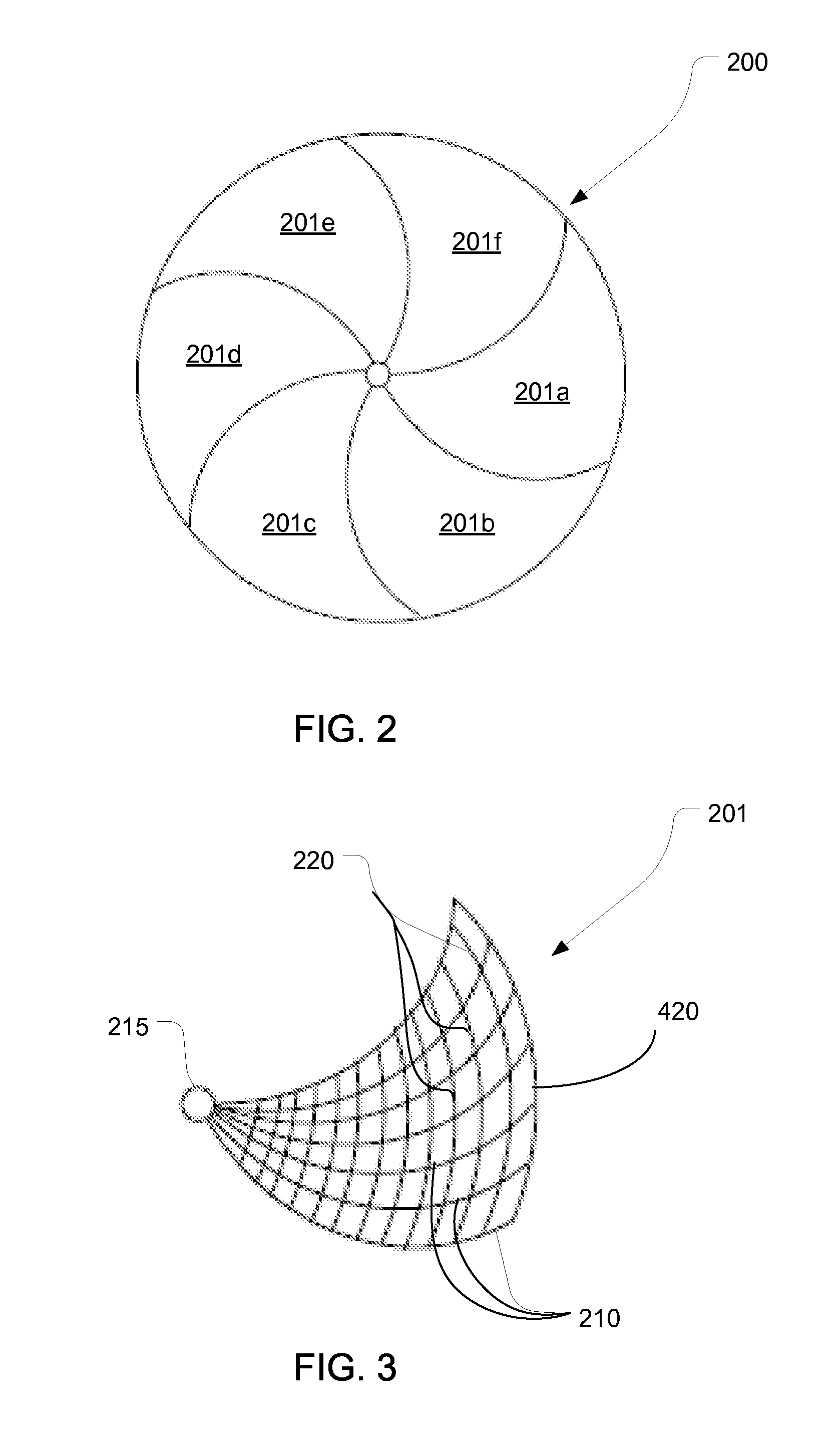
[0024]These electrodes may be a separate layer between the dielectric layer and the insulating layer, or may be embedded in one of these layers. A top view of one embodiment of the chuck 200 is shown in FIG. 2. In this embodiment, the chuck comprises six equally sized regions 201a-f. Of course, a different number of regions may also be used. These regions may be shaped as shown in FIG. 2, or may be any other suitable shape, such as sectors. An electrode is disposed within each region 201a-f. In one embodiment, shown in FIG. 3, each electrode 420 is made up of a pattern of electrically conductive material that is embedded in the dielectric layer or insulating layer of the chuck 200. In some embodiments, this pattern may be a mesh. In some embodiments, the...


PUM


Abstract

An electrostatic chuck is formed using materials that are optically transparent to a range of frequencies, such as infrared radiation. The invention discloses several methods for achieving optical transparency. The chuck electrode can be formed having a mesh pattern designed with a specific open area percentage to provide adequate wafer clamping force while still allowing sufficient levels of infrared radiation to pass through. Alternatively, the chuck electrode can also be made from a transparent conductive film. A workpiece is disposed on one surface of the chuck, and a radiative heat source is positioned on the opposite side of the chuck. A reflector plate may be used to reflect the infrared radiation toward the chuck and the wafer. The spacing of the radiation sources and the shape of the reflector plate may be modified to focus more radiation on a particular portion of the workpiece if desired.

Description

BACKGROUND OF THE INVENTION[0001]Ion implanters are commonly used in the production of semiconductor wafers. An ion source is used to create an ion beam, which is then directed toward the wafer. As the ions strike the wafer, they dope a particular region of the wafer. The configuration of doped regions defines their functionality, and through the use of conductive interconnects, these wafers can be transformed into complex circuits.[0002]As a wafer is being implanted, it is typically clamped to a chuck. This clamping may be mechanical or electrostatic in nature.[0003]This chuck traditionally consists of a plurality of layers. The top layer, also referred to as the dielectric layer, contacts the wafer, and is made of an electrically insulating or semiconducting material, such as alumina, since it must produce the electrostatic field without creating a short circuit. Methods of creating this electrostatic field are known to those skilled in the art and will not be described herein. Fo...

Claims


Application Information

Patent Timeline
IPC IPC(8): H02N13/00H05B1/00
CPCH05B3/0047H01L21/67115H01L21/6831H01L21/68757
Inventor PETRY, KLAUSCARROLL, JAMES
Owner VARIAN SEMICON EQUIP ASSOC INC
Features
  • Generate Ideas
  • Intellectual Property
  • Life Sciences
  • Materials
  • Tech Scout
  • Unparalleled Data Quality
  • Higher Quality Content
  • 60% Fewer Hallucinations
Learn More