Rotor position estimating device, electric motor control system and rotor position estimating method

a technology of energizing control and estimating device, which is applied in the direction of motor/generator/converter stopper, dynamo-electric converter control, dynamo-electric gear control, etc., can solve the problems of difficulty in accurately estimating the rotor position, and reducing the accuracy of energizing control over the synchronous motor. to achieve the effect of accura

Inactive Publication Date: 2014-03-06
TOYOTA JIDOSHA KK
View PDF3 Cites 31 Cited by
  • Summary
  • Abstract
  • Description
  • Claims
  • Application Information

AI Technical Summary

Benefits of technology

[0009]The invention provides a rotor position estimating device, electric motor control system and rotor position estimating method that accurately estimate a rotor position of an electric motor without the influence of an error of a current detector that detects currents flowing through the electric motor.
[0019]According to the first to third aspects of the invention, it is possible to accurately estimate the rotor position of the electric motor including the salient-pole rotor.

Problems solved by technology

However, as described above, with the configuration that detects the rotor position with the use of the rotation position sensor, there occurs an offset error due to an error in the mounting position of the rotation position sensor, and a rotor position that is detected by the rotation position sensor deviates from an actual rotor position.
As a result, the accuracy of energization control over the synchronous motor may be decreased.
Therefore, when there is a deviation in the detected values of the current detector with respect to actual electric motor current values (actual current values), it is difficult to estimate an accurate rotor position.
Thus, the accuracy of energization control over the synchronous motor may decrease.

Method used


Image

  • Rotor position estimating device, electric motor control system and rotor position estimating method
  • Rotor position estimating device, electric motor control system and rotor position estimating method
  • Rotor position estimating device, electric motor control system and rotor position estimating method

Examples


Embodiment Construction

[0027]Hereinafter, an embodiment of the invention will be described in detail with reference to the accompanying drawings. Hereinafter, like reference numerals denote the same or corresponding portions in the drawings, and the description thereof is basically not repeated.

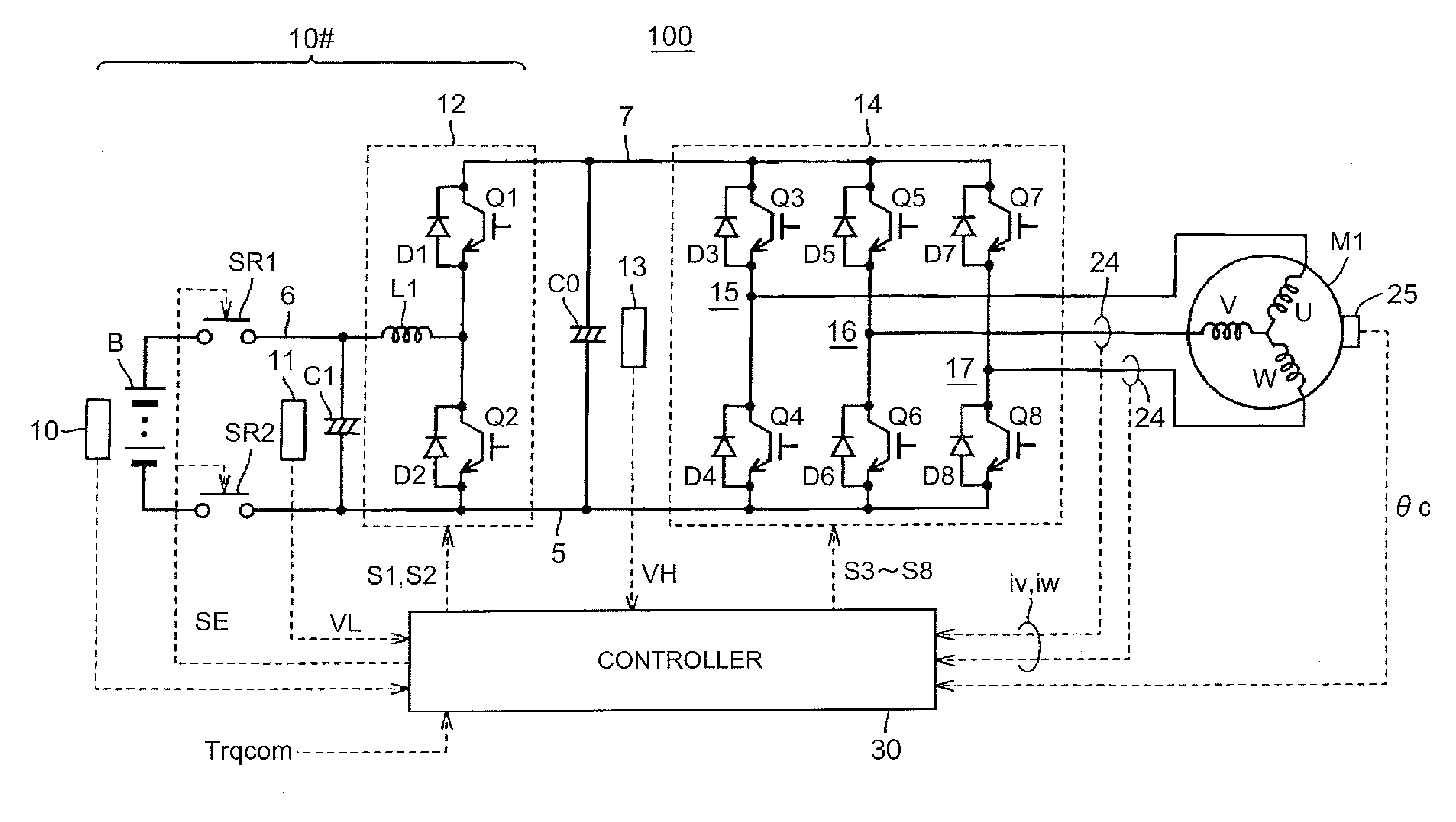
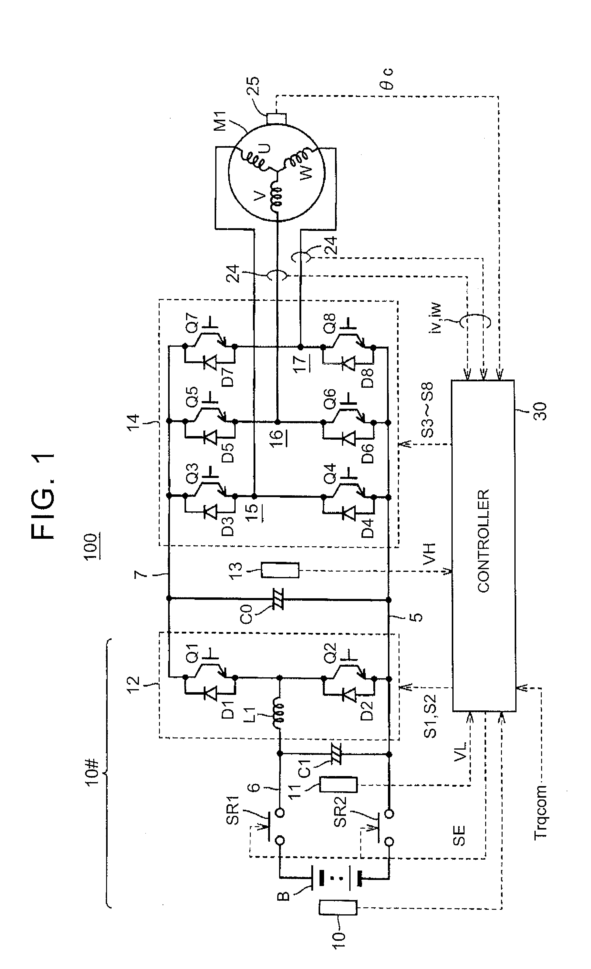
[0028]FIG. 1 is a schematic configuration view of an electric motor control system to which a rotor position estimating device according to the embodiment of the invention is applied.

[0029]The electric motor control system 100 includes a direct-current voltage generating unit 10#, a smoothing capacitor C0, an inverter 14, a controller 30 and an alternating-current motor M1.

[0030]The alternating-current motor M1 is a synchronous motor including a salient-pole rotor. For example, a permanent magnet-type synchronous motor that uses a permanent magnet as a rotor is used as the alternating-current motor M1.

[0031]In the present embodiment, the alternating-current motor M1 is a driving electric motor that generates torque...


PUM


Abstract

A rotor position estimating device includes a voltage application unit, a current detecting unit and an estimating unit. The voltage application unit is configured to apply a d-axis voltage to an electric motor including a salient-pole rotor during a stop of the electric motor. The current detecting unit is configured to detect a q-axis current flowing through the electric motor at the time when the d-axis voltage is applied. The estimating unit is configured to estimate a rotor position during a stop of the electric motor on the basis of the q-axis current detected by the current detecting unit. The voltage application unit is configured to set a voltage application time in correspondence with peak timing at which the q-axis current reaches a peak in a transitional response characteristic of the q-axis current at the time when the d-axis voltage is applied.

Description

INCORPORATION BY REFERENCE[0001]The disclosure of Japanese Patent Application No. 2012-188577 filed on Aug. 29, 2012 including the specification, drawings and abstract is incorporated herein by reference in its entirety.BACKGROUND OF THE INVENTION[0002]1. Field of the Invention[0003]The invention relates to a rotor position estimating device, electric motor control system and rotor position estimating method that estimate a rotor position of an electric motor including a salient-pole rotor.[0004]2. Description of Related Art[0005]In an electromotive vehicle (such as an electric vehicle and a hybrid vehicle) on which an alternating-current motor is mounted as a power source of the vehicle, a synchronous motor, such as a permanent magnet-type synchronous motor that uses a permanent magnet for a rotor, is used as the alternating-current motor. In addition, energization control over the synchronous motor is executed on the basis of information about the position of the rotor. In the ene...

Claims


Application Information

Patent Timeline
Patent Type & Authority Applications(United States)
IPC IPC(8): H02P21/00H02P21/06H02P21/13H02P21/36H02P27/04H02P27/08
CPCH02P21/0096H02P21/04H02P27/085H02P2201/07H02P2209/13H02P21/18H02P21/22
Inventor OYOBE, HICHIROSAINISHIMOTO, TAKUYAOYANAGI, HIROYUKI
Owner TOYOTA JIDOSHA KK
Why Eureka
Try Eureka