Systems and methods for cooling inductive charging assemblies

a charging assembly and inductive charging technology, applied in the field of cooling devices, can solve the problems of reducing fuel economy, reducing performance and/or reducing fuel economy, and affecting the use of peds,

Active Publication Date: 2014-03-06
GENTHERM INC
View PDF4 Cites 81 Cited by
  • Summary
  • Abstract
  • Description
  • Claims
  • Application Information

AI Technical Summary

Benefits of technology

[0007]Recently, it has been proposed to provide certain vehicles (e.g., cars, trucks, tractors, airplanes, boats, and otherwise) with an inductive charging assembly for PEDs. Such a design can allow users to place (e.g., insert) their PED in a dock (e.g., a pad, surface, recess, slot, or otherwise) that has inductive charging functionality, thereby providing inductive charging of the PED without the inconvenience associated with connecting and disconnecting an electrical cord. The dock can comprise an open structure. Alternatively, the dock can be at least partially enclosed, as desired or required.
[0008]One of the byproducts of inductive charging is heat, which can be unwanted in certain situations. For example, heat generated by inductive charging may place an additional load on the heating, ventilating, and air-conditioning system of the vehicle, which can result in decreased performance and / or reduced fuel economy. Further, heat produced by inductive charging may raise the temperature of the PED, which can degrade the performance of the PED and / or make the PED uncomfortable to use. For example, raising the temperature of a cell phone may make the phone uncomfortable to hold and / or to press against the user's ear. Some PEDs even have thermal limits, which shutdown or hinder the functionality of the PED when the PED becomes too hot.

Problems solved by technology

One of the byproducts of inductive charging is heat, which can be unwanted in certain situations.
For example, heat generated by inductive charging may place an additional load on the heating, ventilating, and air-conditioning system of the vehicle, which can result in decreased performance and / or reduced fuel economy.
Further, heat produced by inductive charging may raise the temperature of the PED, which can degrade the performance of the PED and / or make the PED uncomfortable to use.
For example, raising the temperature of a cell phone may make the phone uncomfortable to hold and / or to press against the user's ear.
Some PEDs even have thermal limits, which shutdown or hinder the functionality of the PED when the PED becomes too hot.

Method used


Image

  • Systems and methods for cooling inductive charging assemblies
  • Systems and methods for cooling inductive charging assemblies
  • Systems and methods for cooling inductive charging assemblies

Examples


Embodiment Construction

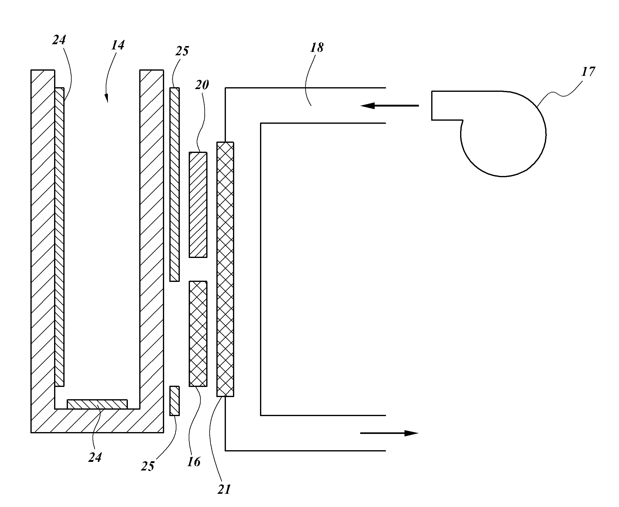
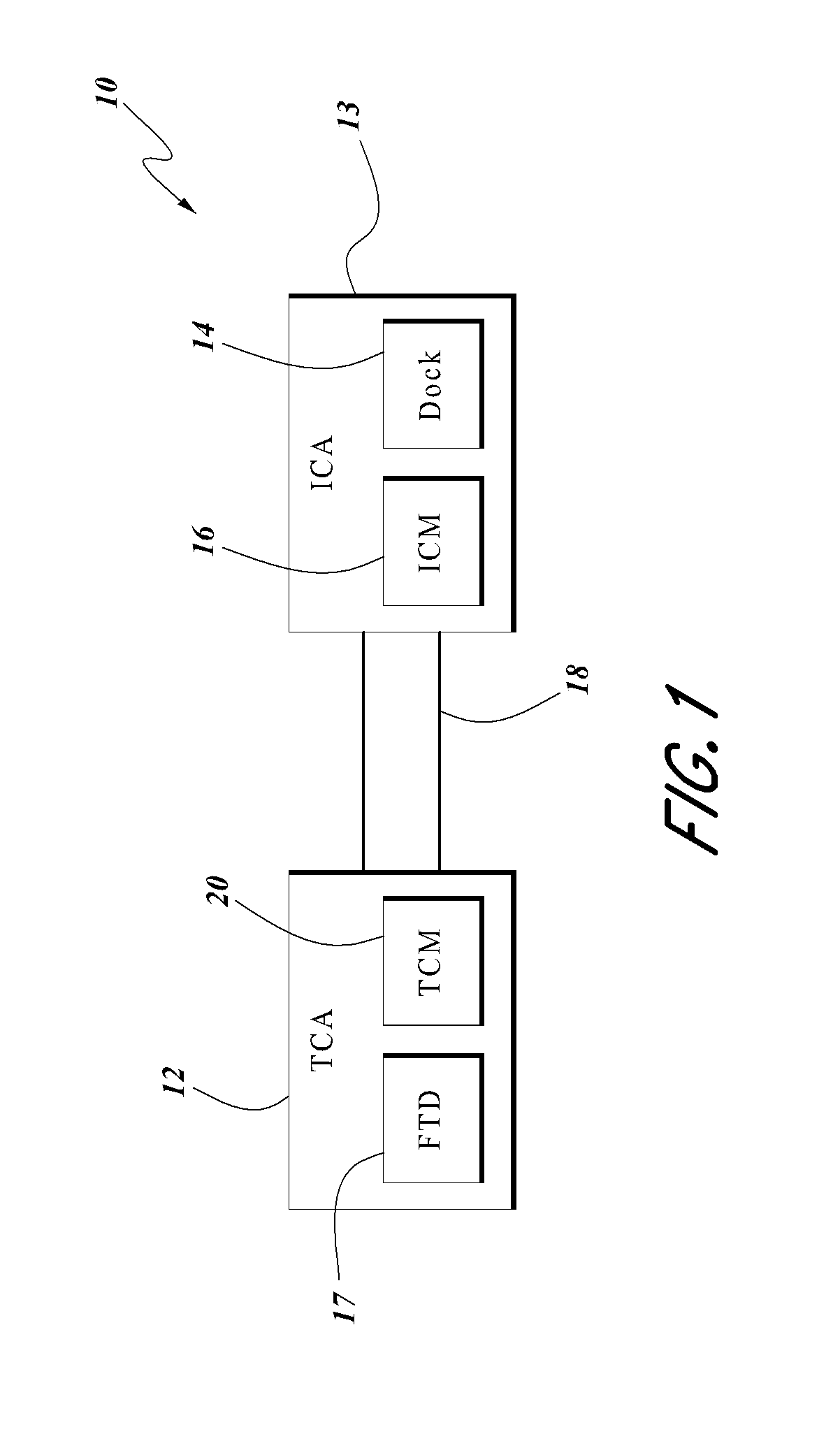
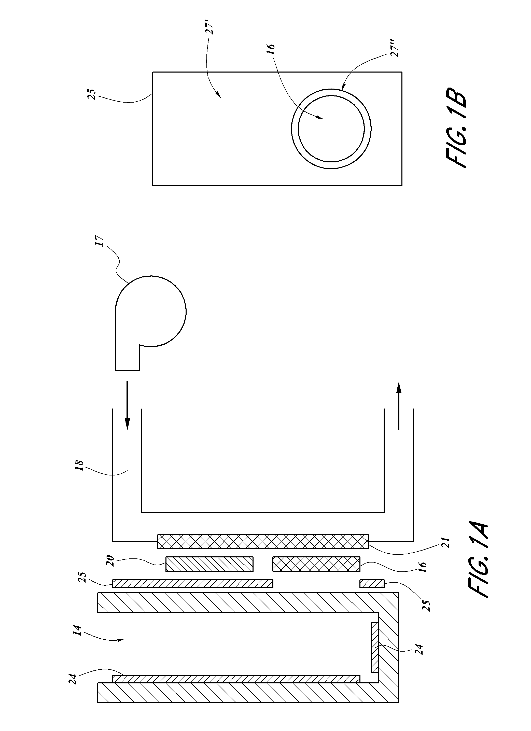
[0056]With reference to FIG. 1, a system 10 for cooling an inductive charger is illustrated. In some embodiments, the system 10 includes a thermal conditioning assembly 12 in thermal communication with an inductive charging assembly 13. In various implementations, the system 10 is located in a vehicle, such as a car, truck, tractor, airplane, ship, train, motorcycle, wheelchair, stroller, wagon, or otherwise. In some embodiments, the system is incorporated, at least partially, into one or more other components of the vehicle (e.g., console, dashboard, other interior portion, etc.). Some variants of the system 10 are included in a generally stationary object, such as a chair, bed, desk, table, or otherwise.

[0057]In certain implementations, the thermal conditioning assembly 12 includes one more of the following: a fluid transfer device 17 (such as, e.g., a pump, blower, or fan), ducting 18 (e.g., a fluid line, coupling, piping, tubing, etc.) thermal conditioning module 20 (e.g., therm...


PUM


Abstract

In some embodiments, a cooling system for an inductive charger includes a thermal conditioning assembly in fluid communication with an inductive charging assembly. The inductive charging assembly can include a dock and an inductive charging module. The dock can be configured to receive a portable electronic device, such as a cell phone, that is configured to accept inductive charging from the inductive charging module. The thermal conditioning assembly can include a fluid transfer device and a thermal conditioning module, such as a thermoelectric device. In various embodiments, heat (e.g., heat produced during inductive charging) can be transferred from the inductive charging assembly to the thermal conditioning module and / or to a fluid flow produced by the fluid transfer device, thereby cooling the inductive charging assembly and / or the portable electronic device.

Description

CROSS-REFERENCE TO RELATED APPLICATIONS[0001]This application claims the priority benefit under 35 U.S.C. §119(e) of U.S. Provisional Application No. 61 / 668,897, filed Jul. 6, 2012, the entirety of which is hereby incorporated by reference.BACKGROUND[0002]1. Field[0003]This application relates to a cooling device and, in some embodiments, to a thermoelectrically cooled inductive charging station, such as for charging a cell phone or other portable electronic devices, and components thereof.[0004]2. Description of the Related Art[0005]Portable electronic devices (PEDs), such as cell phones, music players, sound recorders, computers (e.g., laptops, tablets, etc.), radios, watches, and otherwise, generally require power for operation. As such, many PEDs include a rechargeable battery or other rechargeable power source, thereby allowing for the device to be powered and readily transported without being limited by the length of electrical power cords or the like. In some instances, the c...

Claims


Application Information

Patent Timeline
Patent Type & Authority Applications(United States)
IPC IPC(8): H05K7/20H02J7/02
CPCH02J7/025H05K7/20136H05K7/20145H02J7/0044H02J50/10H05K7/20854H05K7/20209H05K7/20845
Inventor LOFY, JOHNMARQUETTE, DAVID
Owner GENTHERM INC
Why Eureka
Try Eureka