Method for RFID Communication Using Inductive Orthogonal Coupling For Wireless Medical Implanted Sensors and Other Short-Range Communication Applications

a wireless medical and inductive orthogonal coupling technology, applied in the field of biological parameters detection systems, can solve the problems of difficult implementation of implantable medical devices, difficult to achieve high levels of accuracy, and high interference levels, so as to improve the diagnosis and treatment of people, improve the signal-to-noise ratio, and improve the effect of short-term and long-term outcomes

Inactive Publication Date: 2014-03-06
UNIV OF IOWA RES FOUND
View PDF5 Cites 31 Cited by
  • Summary
  • Abstract
  • Description
  • Claims
  • Application Information

AI Technical Summary

Benefits of technology

[0019]Exemplary embodiments disclosed herein would allow a user to place a pressure monitor in the tip of the shunt to monitor pressure inside of the head. In specific embodiments, this information would be transmitted wirelessly to the RFID reader and obviate the need for long and expensive ambulance transfers, subspecialty consultation, and the use of harmful radiation. With this novel signal transduction technique, it is believed that the need for frequent calibration and the problem of data drift will be finally solved. This technology could literally transform the care of this subset of patients.
[0020]Additional benefits may also be realized. For example, if one were to use the transducer disclosed herein to monitor blood sugars, it can be paired with a wearable insulin pump to monitor and treat blood sugars in diabetics. The 25.8 million people in the United States with diabetes would never need to check their blood sugars again. Blood sugar would be wirelessly monitored with this technology and could be automatically corrected. The vastly improved signal-to-noise ratio of this novel transduction technique makes this possible.
[0021]In addition to being used to measure pressure or blood glucose, exemplary embodiments of this technology can be employed to measure pH or tissue oxygen saturation, improving the diagnosis and treatment of people with sepsis or heart failure. It can provide instant feedback on the response to therapy for these critically ill people and improve their short-term and long-term outcomes.

Problems solved by technology

At these frequencies, much wider bandwidths are available, however there is also much higher levels of interference.
This becomes particularly hard to implement for implantable medical devices.
However, in implanted medical device settings, the sensors produce very small amplitude fluctuations in the envelope thereby making it hard to achieve high levels of accuracy.

Method used


Image

  • Method for RFID Communication Using Inductive Orthogonal Coupling For Wireless Medical Implanted Sensors and Other Short-Range Communication Applications
  • Method for RFID Communication Using Inductive Orthogonal Coupling For Wireless Medical Implanted Sensors and Other Short-Range Communication Applications
  • Method for RFID Communication Using Inductive Orthogonal Coupling For Wireless Medical Implanted Sensors and Other Short-Range Communication Applications

Examples


example 1

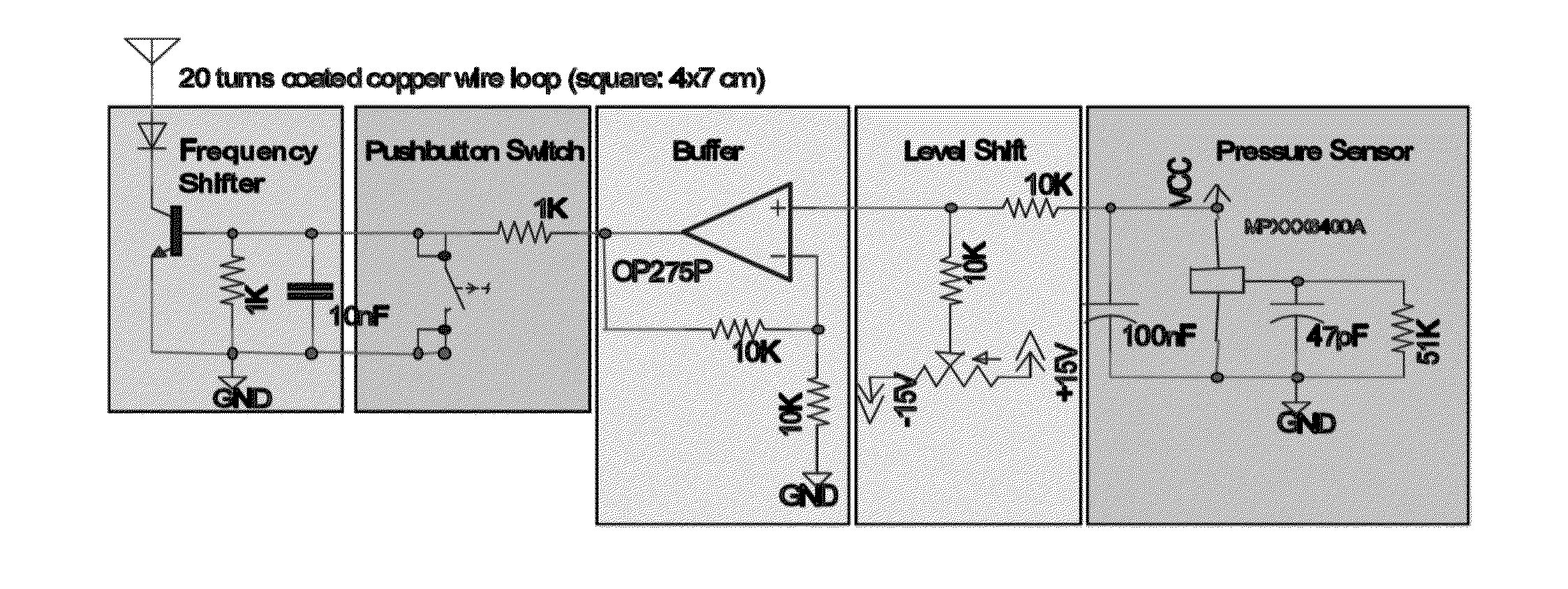
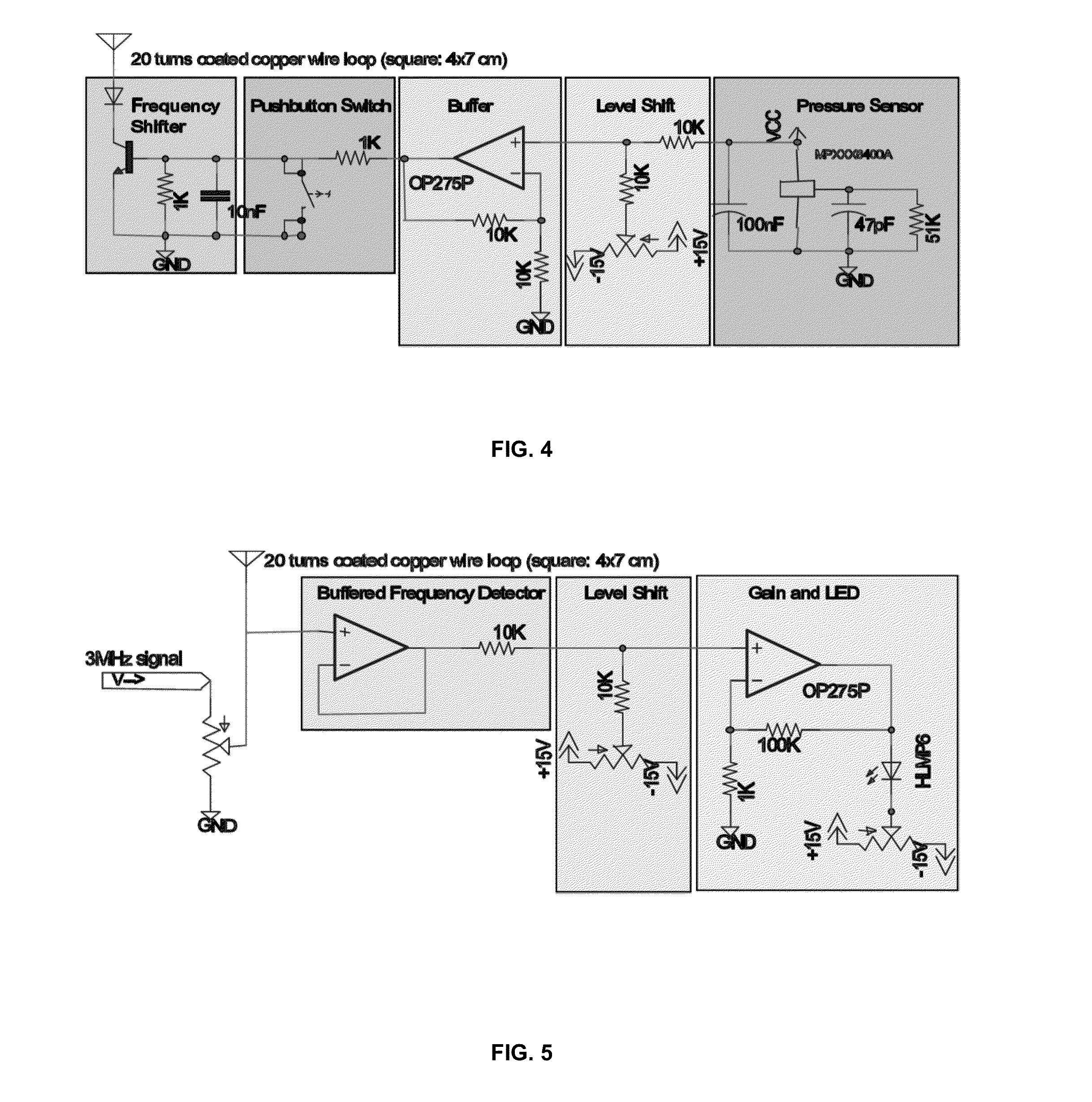
[0069]FIGS. 4-5 are circuit diagrams of reader and tag corresponding to one particular simple embodiment of the invention that uses a simple bipolar transistor as the non-linear impedance and an envelope detector as the detection device. FIGS. 6-7 are general schematics of the system.

[0070]One contemplated design exploits the frequency-dependence of the open-loop gain and common-mode rejection ratio (CMRR) of an inexpensive, low-end operational amplifier. It can be shown (Philips, 1988) that the DC gain of a voltage follower buffer is given by:

A(2CMRR+1)2CMRR(1+A)-A

where A is the open loop gain of the op amp. The frequency-dependence of this A and CMRR results in an offset voltage that varies by nearly 2 volts between 1 MHz and 10 MHz. This varying offset voltage can be used to detect the presence and strength of the harmonics which are introduced by the sensor.

example 2

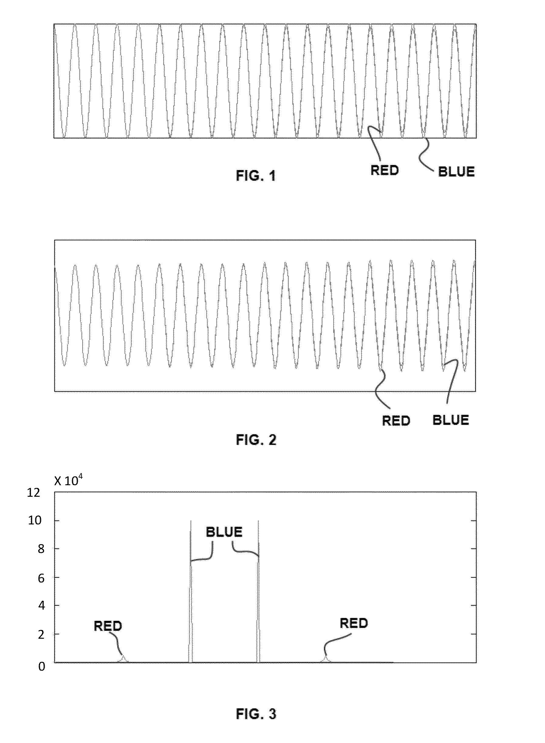
[0071]A reader circuit has a carrier frequency of 3 MHz, and induces a 3 MHz sinusoid on the sender circuit. Pressure Sensor voltage output introduces harmonics of the carrier frequency on the sender circuit. The goal is to determine the pressure based on the induced waveform in the reader circuits. To determine this we looked at the induced frequency spectrum to determine a possible relation between different power levels in each harmonic and pressure. The plots in FIG. 8 indicate power across the frequency spectrum for different pressure levels. The inventors then examined power versus pressure for each of the first 6 harmonics (not including carrier), as shown in FIG. 9.

[0072]To determine a model for this, the inventors tried a few simple functions to fit:

V=a0+a1*Pi+a2*Pi2+a3*Pi

V=a0+a1*Pi+a2*Pi*Pj+a3*Pj

V=a0+a1*Pi+a2*Pj+a3*Pk

V is the sensed signal (pressure sensor voltage), a0, a1, a2 and a3 are constants and P, is the power in the ith harmonic. To fit these models, they used m...


PUM


Abstract

The description provides a signal detection system employing a wireless, passive detection device that utilizes waveform shifting for reporting signals to a reader device. The system is useful for a variety of applications including as an implanted medical device for monitoring patient conditions.

Description

[0001]The present application claims benefit of priority to U.S. Provisional Application Ser. No. 61 / 695,840, filed Aug. 31, 2012, the entire contents of which are hereby incorporated by reference.BACKGROUND OF THE INVENTION[0002]I. Field of the Invention[0003]The invention relates to systems and methods for detecting biologic parameters in a subject, and more particularly to an implantable device system that employs passive transmission and a unique signal transduction process to report in vivo conditions to medical personnel. Specific embodiments include intracranial implantation to measure pressure of cerebral-spinal fluid, blood sugar level monitors, pH sensors and tissue oxygen saturation detectors.[0004]II. Background of the Invention[0005]Radio frequency can be used to transmit information from a transmitter to a receiver. This messaging system can and has taken many formats. Recent advancements in the field have occurred in the short distance transfer of information, resulti...

Claims


Application Information

Patent Timeline
Patent Type & Authority Applications(United States)
IPC IPC(8): A61B5/00G06K7/10G06K19/07
CPCA61B5/0015G06K7/10366G06K19/0717A61B5/0031A61B5/031A61B5/14532A61B5/7225H04B5/0062H04B5/0081
Inventor MUDUMBAI, RAGHURAMANMCCLURG, JOSIAHACHANTA, HEMA K.PIENTA, JOHN N.DASGUPTA, SOURABURESH, CHRISTOPHERDENNING, GERENE
Owner UNIV OF IOWA RES FOUND
Why Eureka
Try Eureka