Battery assembly with adhesive stop mechanism

a technology of stop mechanism and battery, which is applied in the direction of batteries, cell components, electrical devices, etc., can solve the problems of battery cell temperature rise, inability of small number of cells under thermal runaway to propagate into full pack fire, and cell thermal runaway, etc., to achieve the effect of facilitating heat dissipation, enhancing overall heat dissipation efficiency, and large contact surface area

Active Publication Date: 2014-03-06
ATIEVA USA INC
View PDF2 Cites 39 Cited by
  • Summary
  • Abstract
  • Description
  • Claims
  • Application Information

AI Technical Summary

Benefits of technology

[0017]In the battery assembly disclosed herein, the battery cells are housed by the accommodation chambers, and adhesive composition is then added into the assembly through the adhesive application pores. During the adhesive application process, the adhesive composition is confined between the outer layer and the shallow layer by the stop portions and subsequently cured into a bonding layer that firmly holds the battery cells within the accommodation chambers. By virtue of the adhesive stop mechanism, only a small amount of the adhesive composition is needed to secure the battery cells in position. Meanwhile, since the bonding layer is only adhesively attached to the end portions of the battery cells, the respective battery cells are exposed to the heat dissipation ventilation portion to the greatest extent and have a large surface area in contact with air. The overall heat dissipation efficiency is therefore enhanced considerably. In addition, a heat dissipation device may be mounted at both ends of the battery cells, so as to facilitate heat dissipation from the battery cells via both ends thereof.
[0018]By virtue of the arrangement disclosed herein, the battery cells will not easily fall off from the assembly even under severe vibration, thereby preventing the occurrence of accidental disconnection or short circuit and increasing safety during operation. During maintenance, the technicians can simply replace the battery assemblies which contain damaged or low-power battery cells with functional battery assemblies. The overall replacement efficiency is improved and the manpower needed for maintenance works is thus reduced considerably. The invention achieves the objects described above accordingly.

Problems solved by technology

It is unavoidable to have some cells exhibit thermal runaway due to manufacturing defects, assembly defects, or external impact event, but it is not acceptable for the small number of cells under thermal runaway to propagate into full pack fires.
During discharging or charging operations, a battery cell will generate heat, causing a temperature rise in the battery cells.
Hotter battery cell lowers operating life.
Furthermore, battery cell with diminished heat dissipation capacity has an increased risk of thermal runaway, because battery self-heating could gradually build up to higher temperatures, causing electrolyte to decompose, surface electrolyte interface to degenerate, and various other chemical reactions to accelerate until the temperature rises to several hundred degrees Celsius and the cell ruptures and vents with very high temperature gas, over 1,000 degrees Celsius that could ignite adjacent materials.
However, this method consumes a great amount of adhesive glue and increases the manufacture cost.
Meanwhile, since the battery cells are generally covered by adhesive glue, the heat dissipation from the battery cells is largely reduced, thus causing a rise in operating temperature that leads to lower usable life.
In addition, the adhesive bonding area of the cell has lower thermal conductivity, and judicious design of the depth of said adhesive stop changes the heat dissipation capability of the battery cell.
However, extra electrical wiring means extra burden to keep them organized in the compact space of the battery pack.
The management of the complicated electric wires during the replacement, repair and maintenance of battery assemblies is a burdensome and safety hazardous task for installation and maintenance personnel.

Method used


Image

  • Battery assembly with adhesive stop mechanism
  • Battery assembly with adhesive stop mechanism
  • Battery assembly with adhesive stop mechanism

Examples


Embodiment Construction

[0032]The following description is provided to enable any person having ordinary skill in the art to make and use the invention, and is provided in the context of a particular application and its requirements. Various modifications to the embodiments will be readily apparent to those skilled in the art, and the principles defined herein may be applied to other embodiments and applications without departing from the spirit and scope of the invention. Thus, the present invention is not intended to be limited to the embodiments shown, but is to be accorded the widest scope consistent with the principles, features and teachings disclosed herein.

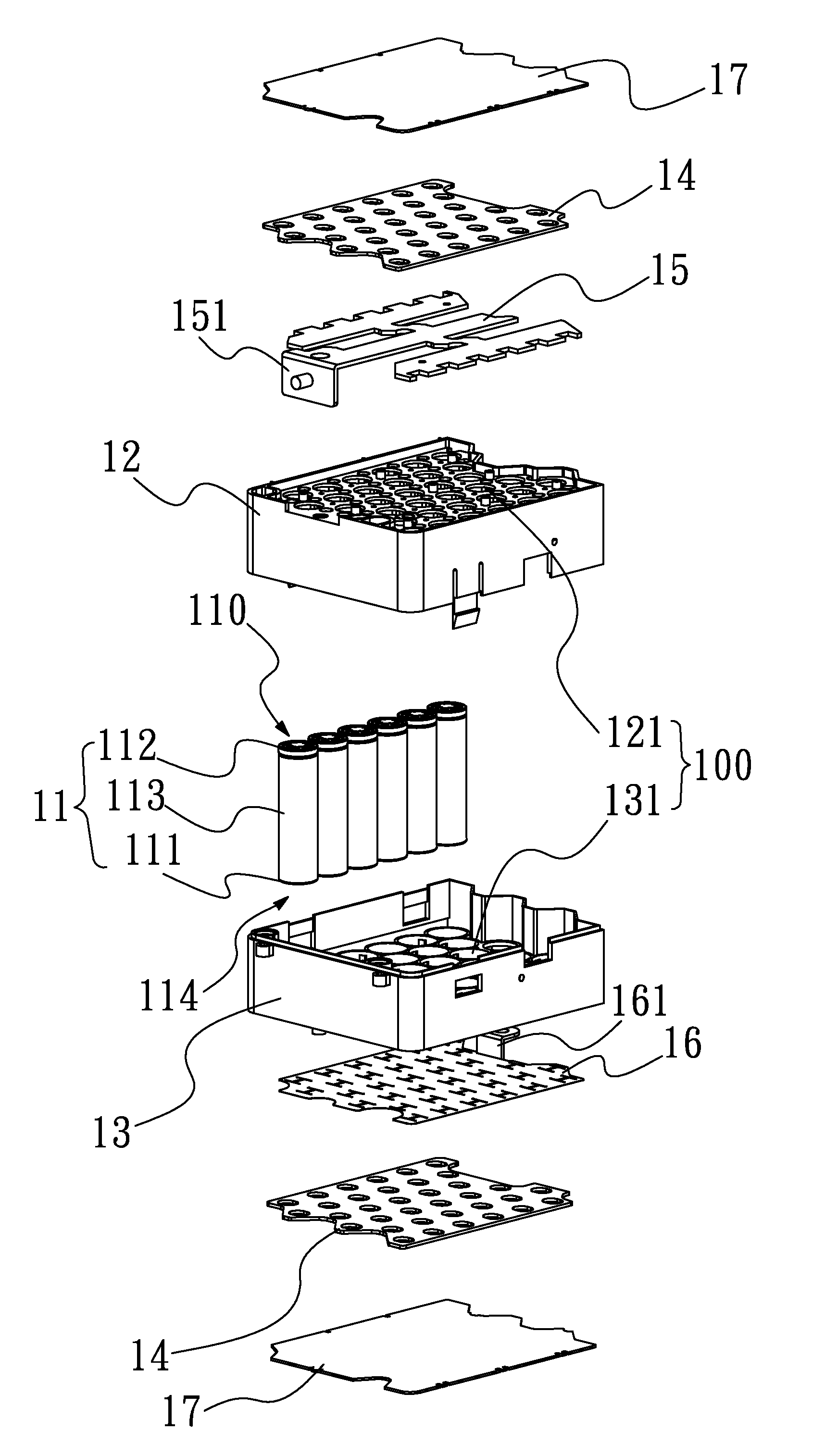
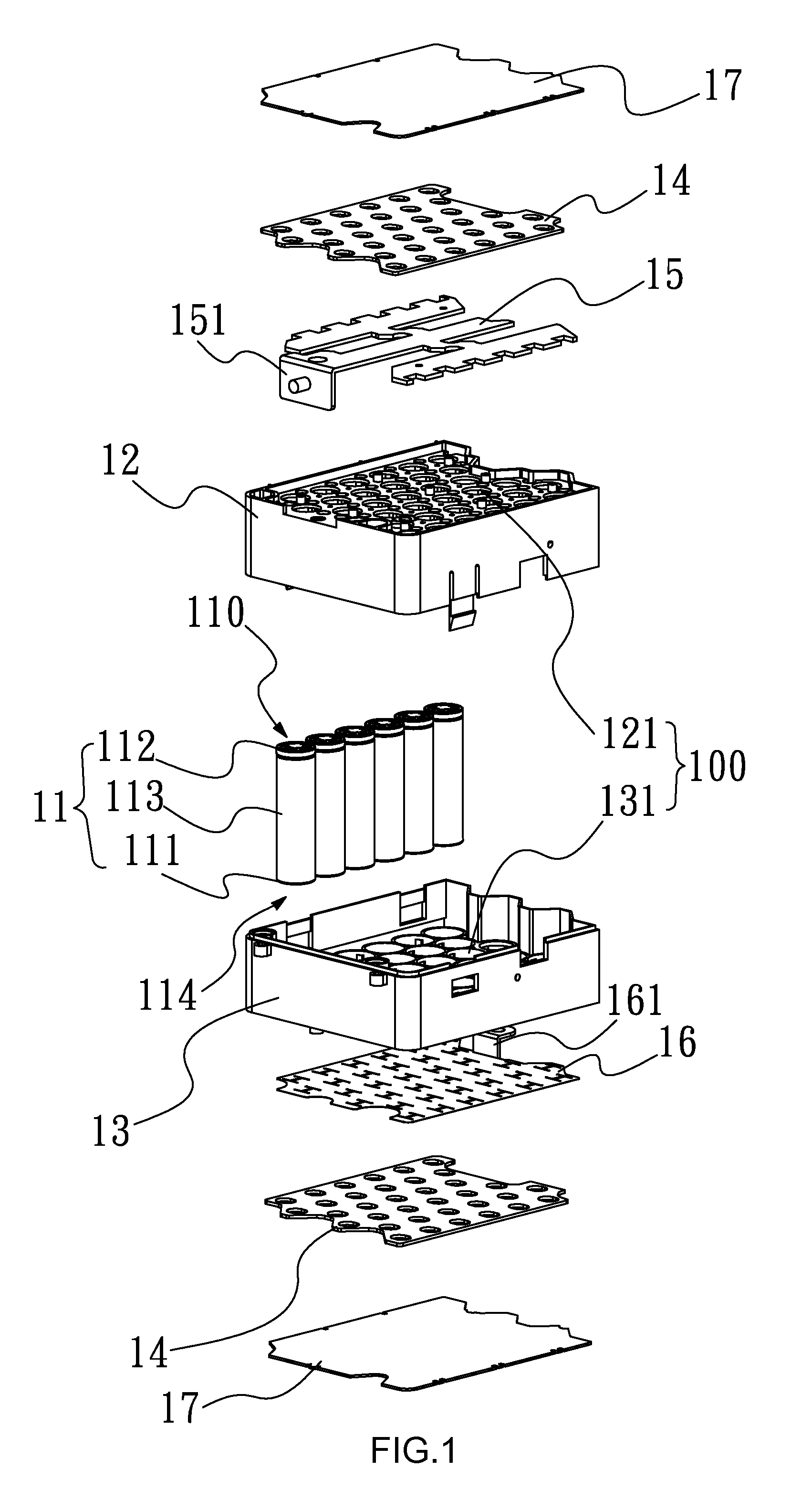
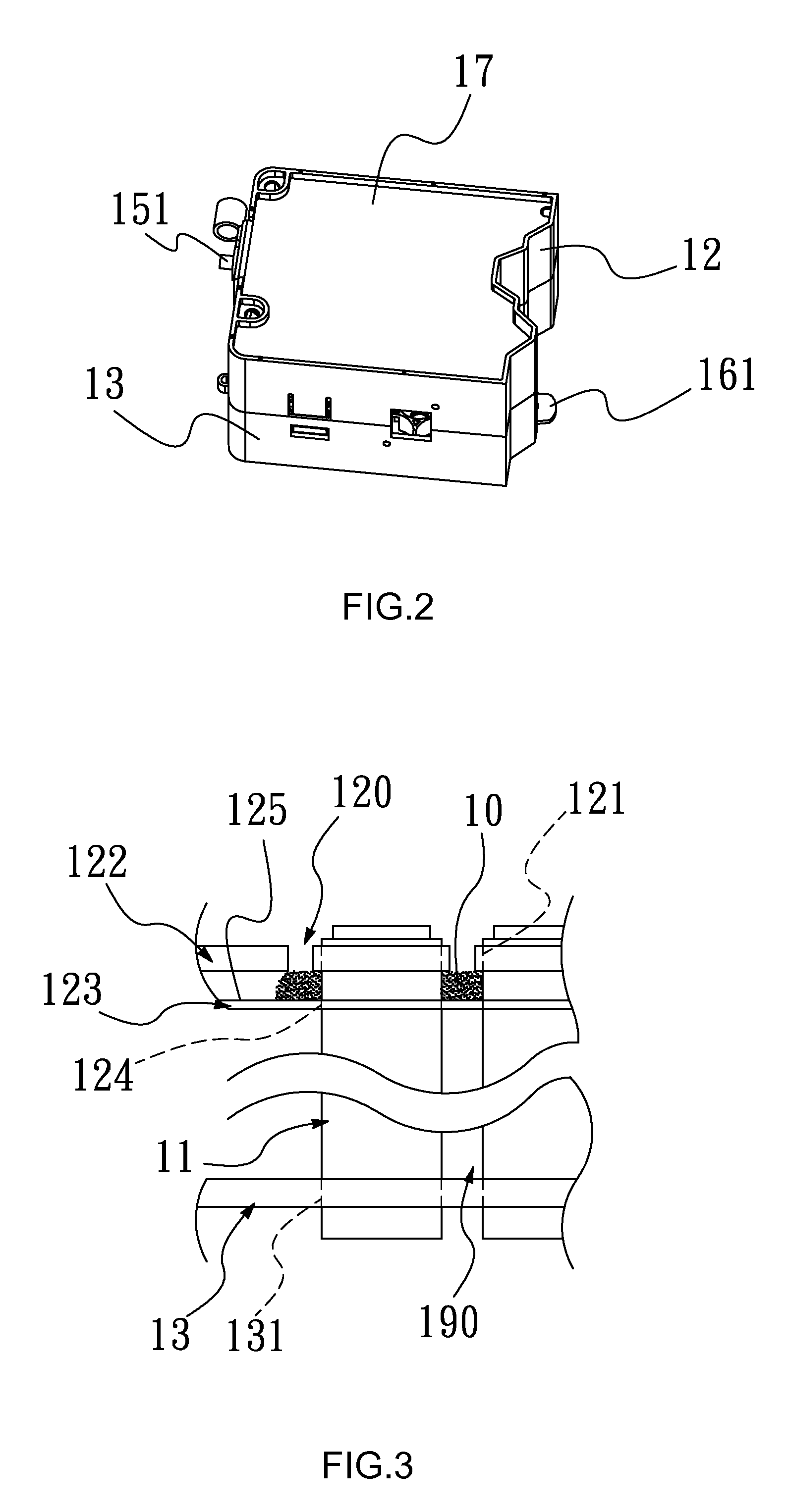
[0033]FIGS. 1, 2 and 3 show the battery assembly according to the first preferred embodiment of the invention, whose frames comprise an adhesive stop mechanism. The battery assembly comprises multiple battery cells 11, a primary retaining frame 12, a secondary retaining frame 13, a common electrode and a bonding layer 10. The common electrode is ...


PUM

PropertyMeasurementUnit
temperatureaaaaaaaaaa
thermal conductivityaaaaaaaaaa

Abstract

A battery assembly provided with an adhesive stop mechanism is disclosed. The battery assembly includes multiple battery cells, a primary retaining frame, a secondary retaining frame, two common electrodes and a bonding layer. The primary and second retaining frames are combined together to constitute accommodation chambers for housing the battery cells. The primary retaining frame includes an outer deck and a shallow deck, wherein the outer deck is formed with adhesive application pores and the shallow deck is formed with stop portions corresponding to the adhesive application pores. The adhesive composition applied through the adhesive application pores is confined by the stop portions and subsequently cured into a bonding layer that firmly holds the battery cells within the accommodation chambers.

Description

FIELD OF THE INVENTION[0001]The present invention relates to a battery assembly with multiple battery cells and, more particular, to a battery assembly whose frames are provided with an adhesive stop mechanism.BACKGROUND OF THE INVENTION[0002]Given the risk of increasing carbon emissions when using a pollution-generating energy source with limited reserves, such as fossil oil and natural gas, high-tech industries are pursuing replacement of the traditional energy sources with renewable and clean energy sources, including solar energy, hydraulic energy and wind energy. With this trend, vehicles with electric propulsion are being deployed in place of conventional internal combustion cars. The development of electric-powered vehicles has thus attracted great interest in the related fields.[0003]An electric-powered vehicle requires a large quantity of power for long-distance running and, therefore, must be equipped with a good number of battery cells in its energy source. For a compact ...

Claims


Application Information

Patent Timeline
Patent Type & Authority Applications(United States)
IPC IPC(8): H01M2/10H01M50/213H01M50/244H01M50/249H01M50/262H01M50/264H01M50/289
CPCH01M2/1083H01M10/613H01M10/617H01M10/625H01M10/6554H01M10/6557H01M10/6563H01M50/579H01M50/289H01M50/262H01M50/213Y02E60/10H01M10/615H01M10/6562H01M10/6551H01M2220/20
Inventor CHUANG, CHIA-MINGLIU, TAI-TSUN
Owner ATIEVA USA INC
Why Eureka
Try Eureka