Pressure based mass flow controller

a mass flow controller and pressure-based technology, applied in the field of semiconductor processing, can solve the problems of high cost of space in a modern semiconductor tool, the form factor common to thermal and pressure-based mfcs, and the need for high performance of conventional mfcs, so as to save space and improve functionalities.

Active Publication Date: 2014-03-13
ICHOR SYST INC
View PDF8 Cites 25 Cited by
  • Summary
  • Abstract
  • Description
  • Claims
  • Application Information

AI Technical Summary

Benefits of technology

[0011]The present invention addresses these shortcomings by providing a pressure based mass flow controller (MFC) device, and methods therein, with space saving layouts and improved functionalities.

Problems solved by technology

Problematically, as more refined manufacturing processes evolved with time, higher performance was needed from conventional thermal and pressure based MFCs.
The stability and accuracies of the past devices were bottlenecking semiconductor fabrication process.
The relatively long transient time to change gas flow rates to the process once acceptable with the longer process steps is problematic with the shorter process steps.
One of the issues common to thermal and pressure based MFCs is form factor.
Space is very expensive in a modern semiconductor tool.

Method used


Image

  • Pressure based mass flow controller
  • Pressure based mass flow controller
  • Pressure based mass flow controller

Examples


Embodiment Construction

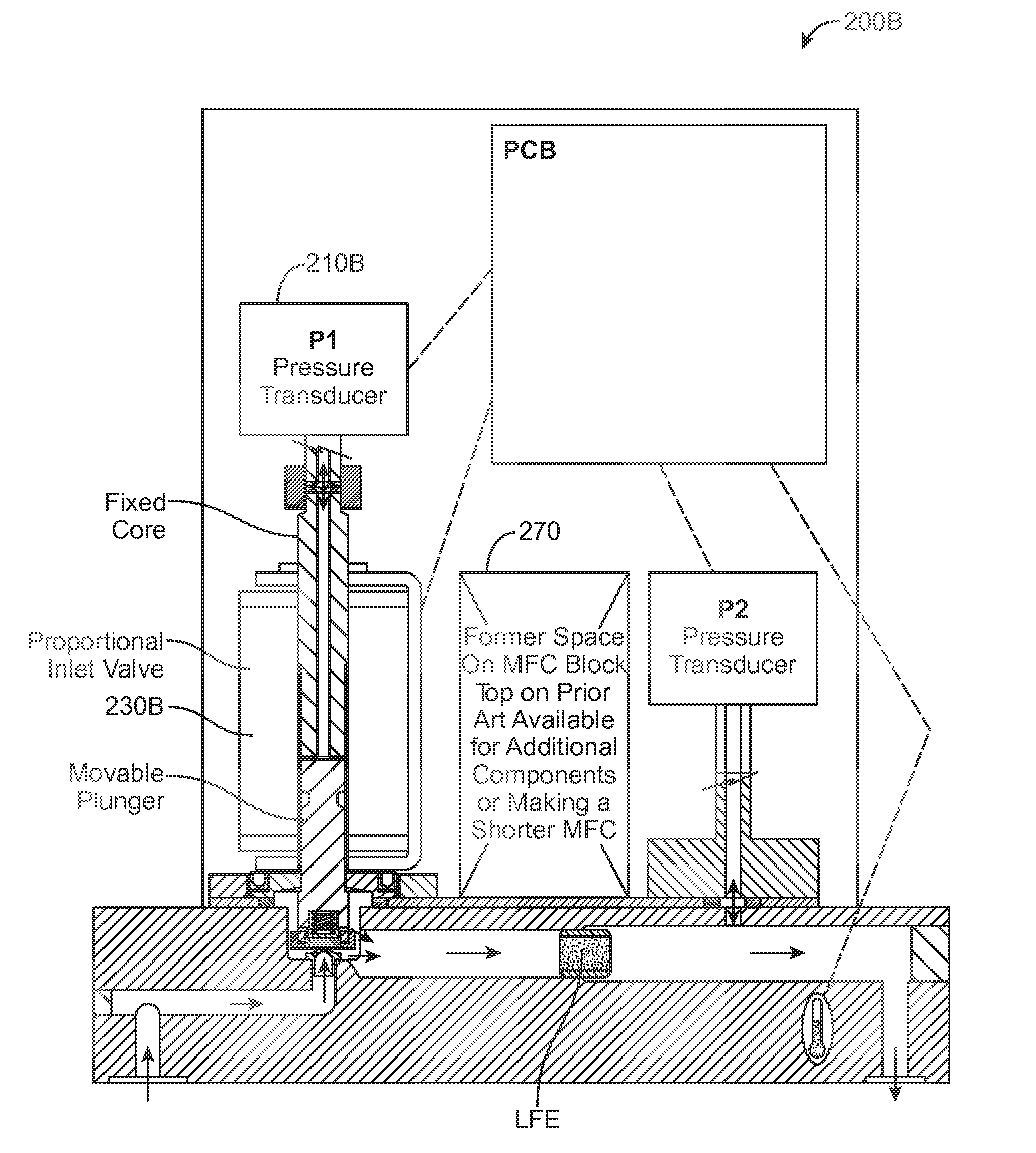
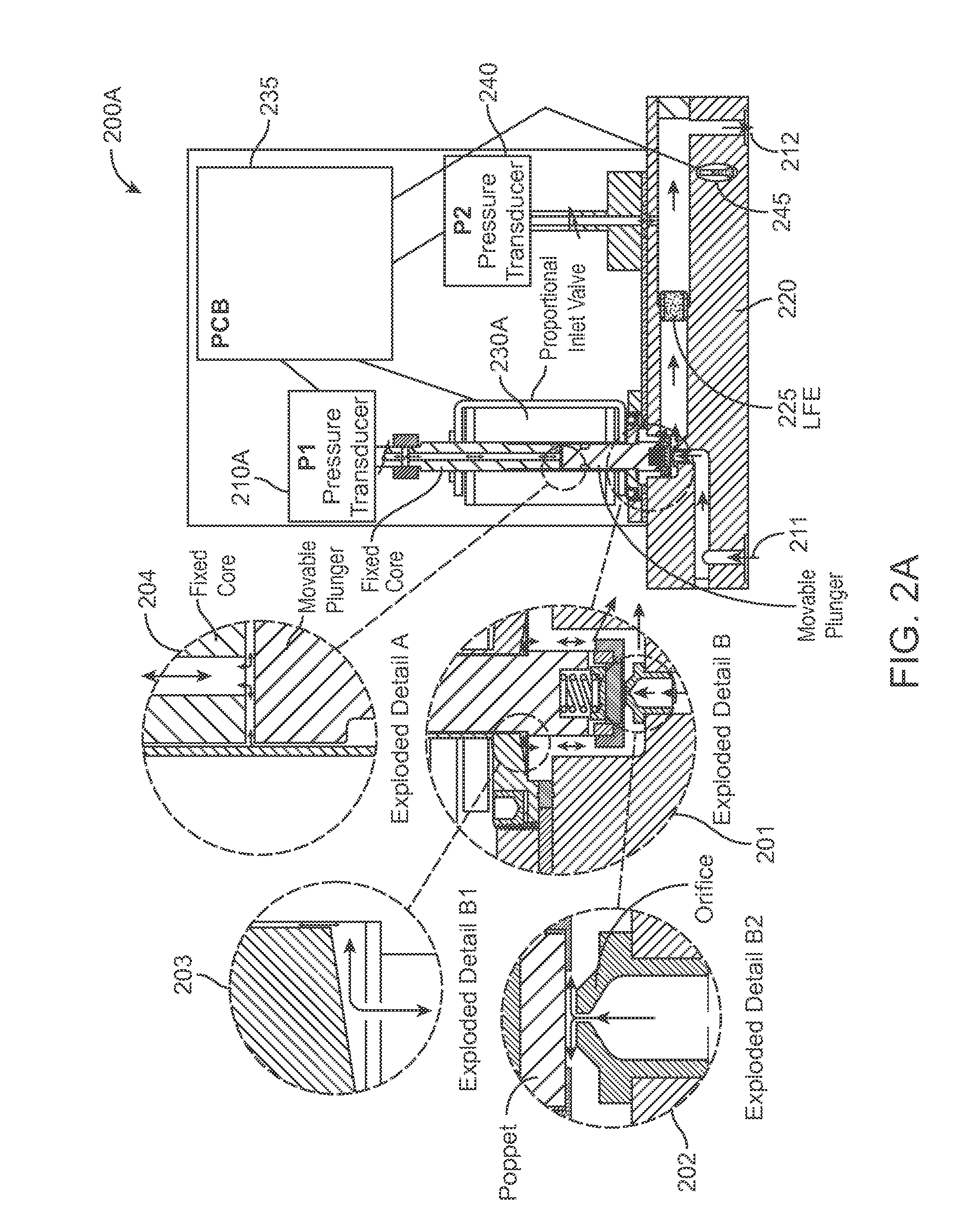
[0030]A mass flow controller (MFC) device, and methods therein, with various space saving layouts is described.

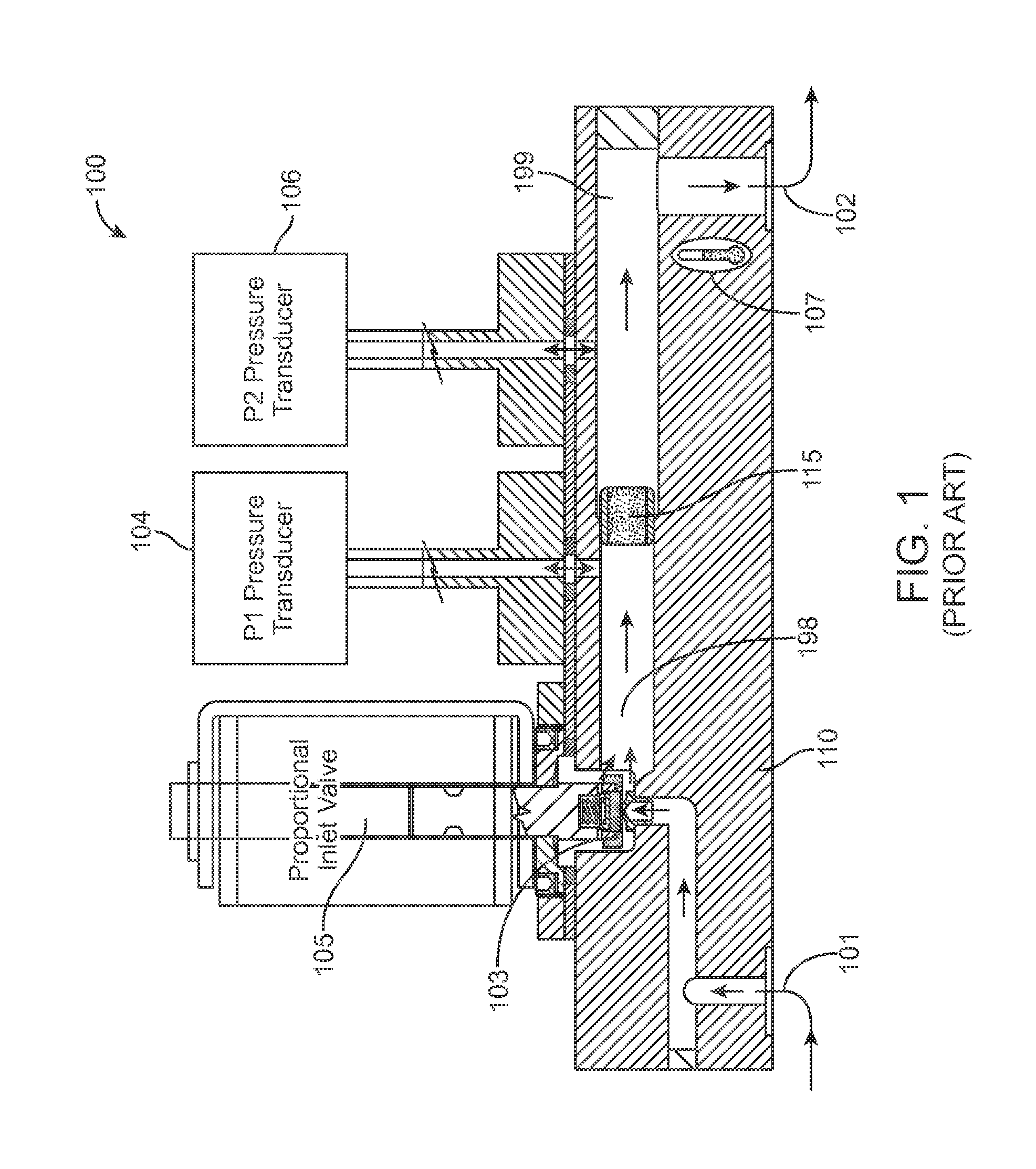
[0031]FIG. 1 is a schematic diagram illustrating a prior art layout of a pressure based mass flow controller (MFC) 100 with a conventionally-located P1 pressure transducer 104 coupled to a base 220 within a standard envelope, according to a prior art embodiment. One example of the prior art MFC 100 is the device manufactured by Fugasity. The prior art MFC 100 can be 4.13″ long to fit industry standards. It consists of a proportional flow control valve 105 at an inlet 101 of the device, followed by the P1 pressure transducer 104 downstream of a proportional flow control valve 105, followed by a characterized laminar flow element (LFE) 105 acting as a flow restrictor, and a P2 pressure transducer 106 near the outlet 102 of the device. The prior art MFC 100 also utilizes a printed control board (PCB) (not shown) containing supporting electronics, software and calibration coeff...


PUM


Abstract

A mass flow controller (MFC) has a standard envelope with an enclosure and a corresponding base. A pressure transducer is communicatively coupled to a process gas in a proportional inlet valve without being physically coupled to the base. The space formerly occupied by the pressure transducer is available for additional component integration, or reduction of the standard envelope size. A second pressure transducer is located remotely and shared by multiple MFCs. A relief valve can quickly relieve a P1 pressure of a P1 volume of process gas. A first laminar flow element (LFE) and a second LFE and in series high conductance valve configured in parallel to produce a wide-range MFC that maintains accuracy.

Description

CROSS-REFERENCE TO RELATED APPLICATIONS[0001]This application claims the benefit of priority under 35 U.S.C. 119(e) to U.S. Application No. 61 / 743,748, filed Sep. 10, 2012, entitled PRESSURE BASED MASS FLOW CONTROLLER, by Daniel T. Mudd et al., the contents of which are hereby incorporated by reference in its entirety.FIELD OF THE INVENTION[0002]The invention relates generally to semiconductor processing, and more specifically, improved mass flow controllers (MFC).BACKGROUND OF THE INVENTION[0003]Mass flow control has been one of the key technologies in semiconductor chip fabrication for forty years. As the technology of chip making has improved so has the demand on the mass flow controller (MFC). Initially chip manufacturing processes were courser than today. Process steps were longer and focus was on the control of steady state flow accuracies and repeatability. One could divert the gas flow or wait to strike a plasma until the system had stabilized at steady state and little atte...

Claims


Application Information

Patent Timeline
Patent Type & Authority Applications(United States)
IPC IPC(8): G05D7/06
CPCG05D7/0635Y10T137/776
Inventor MUDD, DANIEL T.MUDD, PATTI J
Owner ICHOR SYST INC
Why Eureka
Try Eureka