Intake Enhancement System for Vehicle

Inactive Publication Date: 2014-03-13
BURKE FREDERICO
View PDF0 Cites 2 Cited by
  • Summary
  • Abstract
  • Description
  • Claims
  • Application Information

AI Technical Summary

Benefits of technology

This patent describes an intake enhancement system for vehicles that uses existing air conditioning or an intercooler to cool down the combustion element, while improving the heat exchange between the combustion element and the vehicle's heat exchanger. The system does not require any modifications to the vehicle's structure or complicated mechanical components, resulting in a cost-effective and efficient solution for incorporating in any existing vehicle. Overall, this patent provides an economical and efficient way to improve engine performance by cooling down the combustion element before it reaches the engine.

Problems solved by technology

It is a scientific fact that an internal combustion engine operates less efficiently at warmer ambient temperatures.
Accordingly, warmer air intake combined with warm fuel creates a potentially lean condition or “vapor lock” that can damage the engine.
However, the heat shield can only prevent the airflow being heated up by the heat generated from the engine; it does not cool down the airflow before the airflow enters into the engine.

Method used


Image

  • Intake Enhancement System for Vehicle
  • Intake Enhancement System for Vehicle
  • Intake Enhancement System for Vehicle

Examples


second embodiment

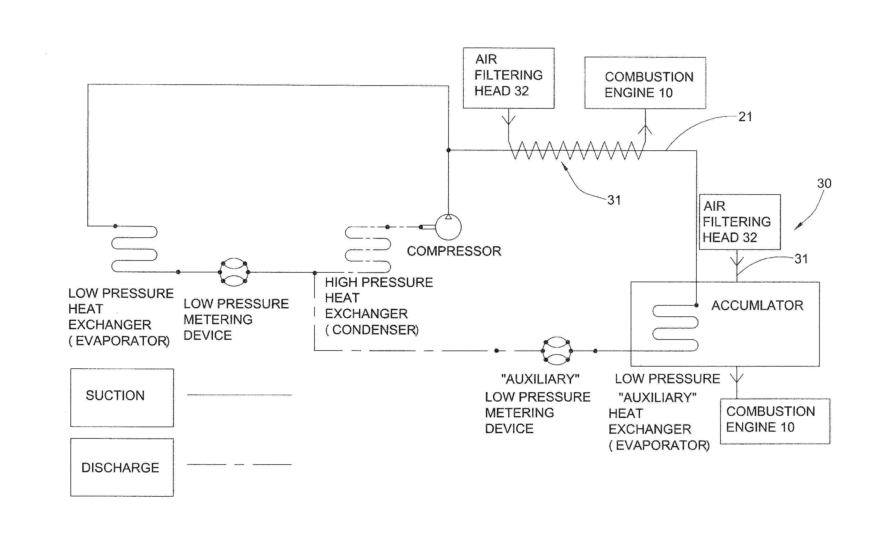
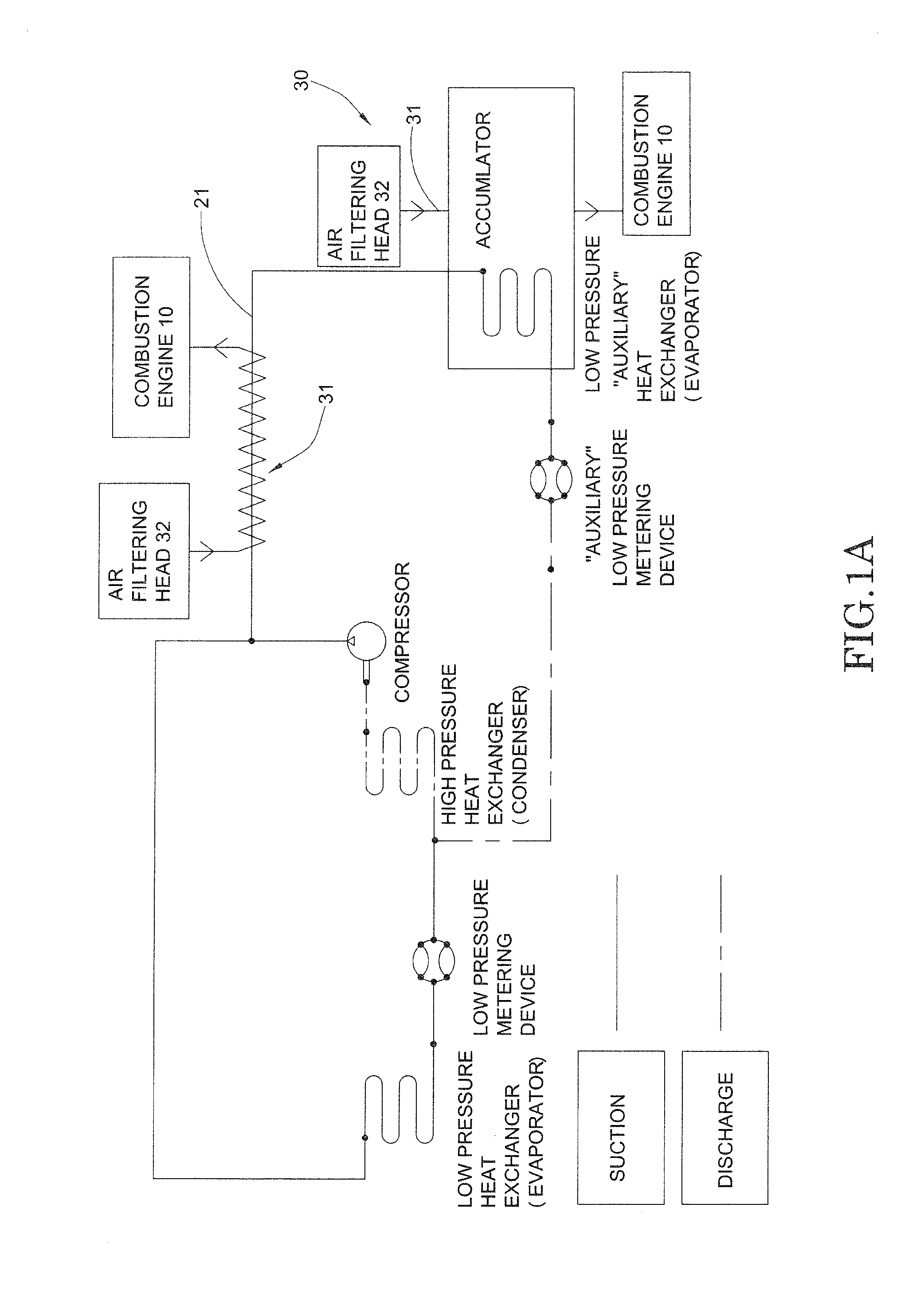
[0082] in order to detour the heat exchanging agent, the intake cooling unit 30′ further comprises a cooling extension duct 33′ for operatively extending from the heat exchanging duct 21′ to detour a flow of the heat exchanging agent, wherein the cooling extension duct 33′ can be spirally extended along the delivering duct 31′ to heat-exchange the combustion element with the heat exchanging agent.

[0083]The cooling extension duct 33′ has two ends operatively coupled with a suction section of the heat exchanging duct 21′ especially at the low pressure side of the heat exchanger 20′. Instead of directly guiding the heat exchanging agent to flow along the heat exchanging duct 21′, the heat exchanging agent is guided to detour from the heat exchanging duct 21′ to the cooling extension duct 33′ and is then guided to flow back to the heat exchanging duct 21′.

[0084]The combustion element will heat-exchange with the heat exchanging agent through the thermal conduction between the delivering ...

third embodiment

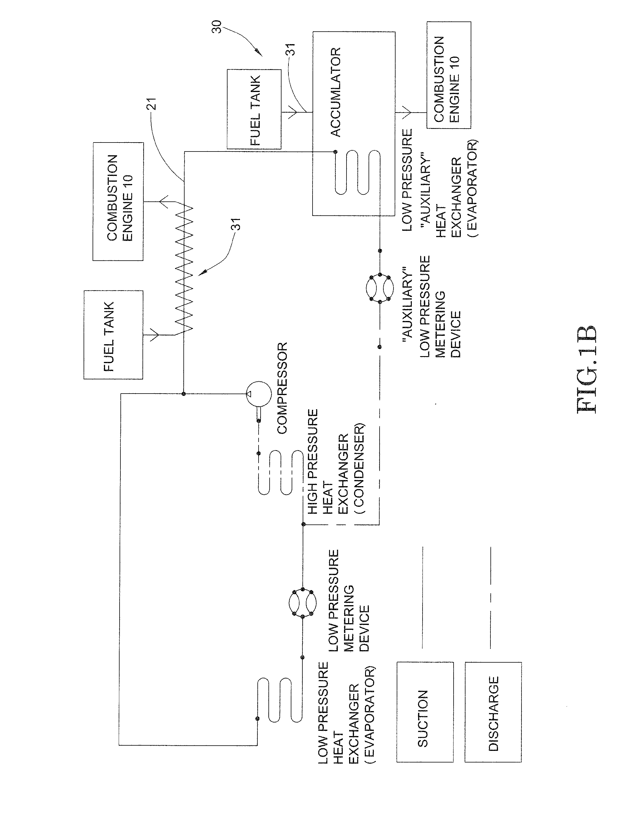
[0119]FIGS. 12 and 13 are the first modification of the third embodiment, wherein the cooling agent is arranged to cool the fuel as the combustion element before the fuel enters into the combustion engine 12A. Accordingly, the fuel line is operatively linked to the fuel tank 11A with the combustion engine 12A for delivering fuel from fuel tank 11A to the combustion engine 12A.

[0120]As shown in FIGS. 12 and 13, the intake enhancement system further comprises at least a fuel rail 40A provided at the cooling line 33A for enabling the cooling agent heat-exchanging with the fuel before the fuel enters into the combustion engine 12A.

[0121]As shown in FIGS. 24 and 25, the fuel rail 40A has a fuel-engine channel 41A operatively link to the fuel line to guide the fuel to flow from the fuel line into the combustion engine 12A, and a cooling agent channel 42A operatively linked to the cooling line 33A to guide the cooling agent to flow through the cooling agent channel 42A. The fuel-engine cha...


PUM


Abstract

An intake enhancement system for a vehicle includes a chiller bath, a delivering line operatively extended from the chiller bath for tapping at a heat exchanging line of a HVAC system to guide a heat exchanging agent flowing between the chiller bath and the HVAC system, and a cooling line operatively extended from the chiller bath for guiding a cooling agent to flow from the chiller bath toward the combustion engine. The chiller bath provides a heat-exchanging place for cooling the cooling agent by the heat exchanging agent. Therefore, the cooling agent is guide to cool the combustion element before the combustion element enters into the combustion engine for enhancing an efficiency of the combustion engine.

Description

CROSS REFERENCE OF RELATED APPLICATION[0001]This is a Continuation-In-Part application that claims the benefit of priority under 35 U.S.C. §119 to a non-provisional application, application Ser. No. 13 / 135,062, filed Jun. 24, 2011.NOTICE OF COPYRIGHT[0002]A portion of the disclosure of this patent document contains material which is subject to copyright protection. The copyright owner has no objection to any reproduction by anyone of the patent disclosure, as it appears in the United States Patent and Trademark Office patent files or records, but otherwise reserves all copyright rights whatsoever.BACKGROUND OF THE PRESENT INVENTION[0003]1. Field of Invention[0004]The present invention relates to a vehicle fuel system, and more particularly to an intake enhancement system, which substantially cools the air / fuel intake before the air / fuel enters into the internal combustion engine so as to maximize the efficiency of the internal combustion engine.[0005]2. Description of Related Arts[0...

Claims


Application Information

Patent Timeline
IPC IPC(8): B60H1/00F02B51/00
CPCF02B51/00B60H1/00028F01P3/20F02B29/0443F02M31/20B60H1/143B60H2001/00307Y02T10/12
Inventor BURKE, FREDERICO
Owner BURKE FREDERICO
Why Eureka
Try Eureka