Anti-icing, de-icing, and heating configuration, integration, and power methods for aircraft, aerodynamic, and complex surfaces

a technology of heating configuration and integration, applied in the direction of substantially flat resonant elements, resonance antennas, transportation and packaging, etc., can solve the problems of undesirable and/or dangerous flying performance, excessive weight of airfoil configuration, and ice build-up on the leading edge surface, so as to reduce the need for batteries, and improve the effect of energy efficiency

Active Publication Date: 2014-03-13
BATTELLE MEMORIAL INST
View PDF20 Cites 80 Cited by
  • Summary
  • Abstract
  • Description
  • Claims
  • Application Information

AI Technical Summary

Benefits of technology

[0017]The inventive aspects that employ a capacitor to power a resistive heater can provide significant advantages in terms of energy efficiency (for example, utilizing excess energy) and reduced weight since it can reduce the need for batteries.
[0018]In a further aspect, the invention provides a method making an airfoil comprising insulated electrical leads for powering a CNT heater system wherein, channels are machined or molded into the airfoil surface, and pre-formed electrical insulators are installed into these channels, and electrical power leads are installed into the insulators and contacting the electric leads to a CNT heater layer. Preferably, the pre-formed electrical insulators are made from a flexible plastic such as polyethylene. In another preferred embodiment, the channel allows for the electrical leads to remain flush with the outer wing surface when installed so as not to disrupt the aerodynamic properties of the airfoil shape. Preferably, the pre-formed electrical insulator completely encases the electrical lead where it passes through the hole in the airfoil (typically an aircraft wing). Also, preferably, the pre-formed electrical insulator is open on top of the channel area allowing for the electrical leads to contact with the CNT heater layer along its length; in preferred embodiments, the electrical insulator is open for a continuous length of at least 3 cm (in some embodiments at least 10 cm), and the electrical lead is in direct contact with the CNT heater layer for the length of at least 3 cm. In some preferred embodiments, the electrical lead comprises a porous metal such as copper mesh or braided copper wires for superior contact with the CNT layer.

Problems solved by technology

Forward facing aerodynamic surfaces, for example, wind turbines, propeller spinners, radomes, when exposed to atmospheric icing conditions are susceptible to ice build-up on the leading edge surface.
If not removed, this accumulated ice can add excessive weight to the structure and alter the airfoil configuration.
For aircraft airfoils, this can cause undesirable and / or dangerous flying performance.
Ice build-up on the outside surface of a radome causes undesirable attenuation and distortion of the transmitted electromagnetic waves.
A portion of the capacitive AC associated with the alternating electric field is present in the interfacial ice as conductivity (resistive) AC, which causes dielectric loss heating.
A major concern with traditional leading edge heating systems is the problem when the melt water re-freezes as it flows backwards outside of the front heated panel.

Method used


Image

  • Anti-icing, de-icing, and heating configuration, integration, and power methods for aircraft, aerodynamic, and complex surfaces
  • Anti-icing, de-icing, and heating configuration, integration, and power methods for aircraft, aerodynamic, and complex surfaces
  • Anti-icing, de-icing, and heating configuration, integration, and power methods for aircraft, aerodynamic, and complex surfaces

Examples


Embodiment Construction

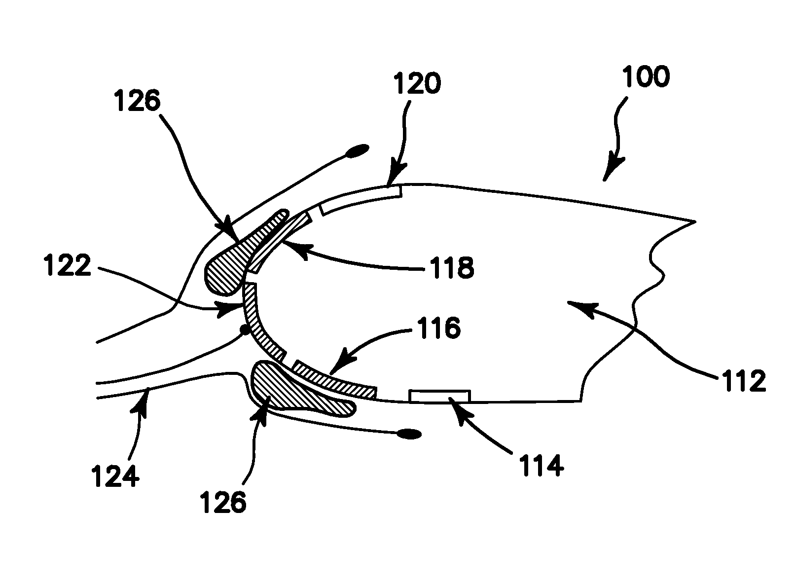
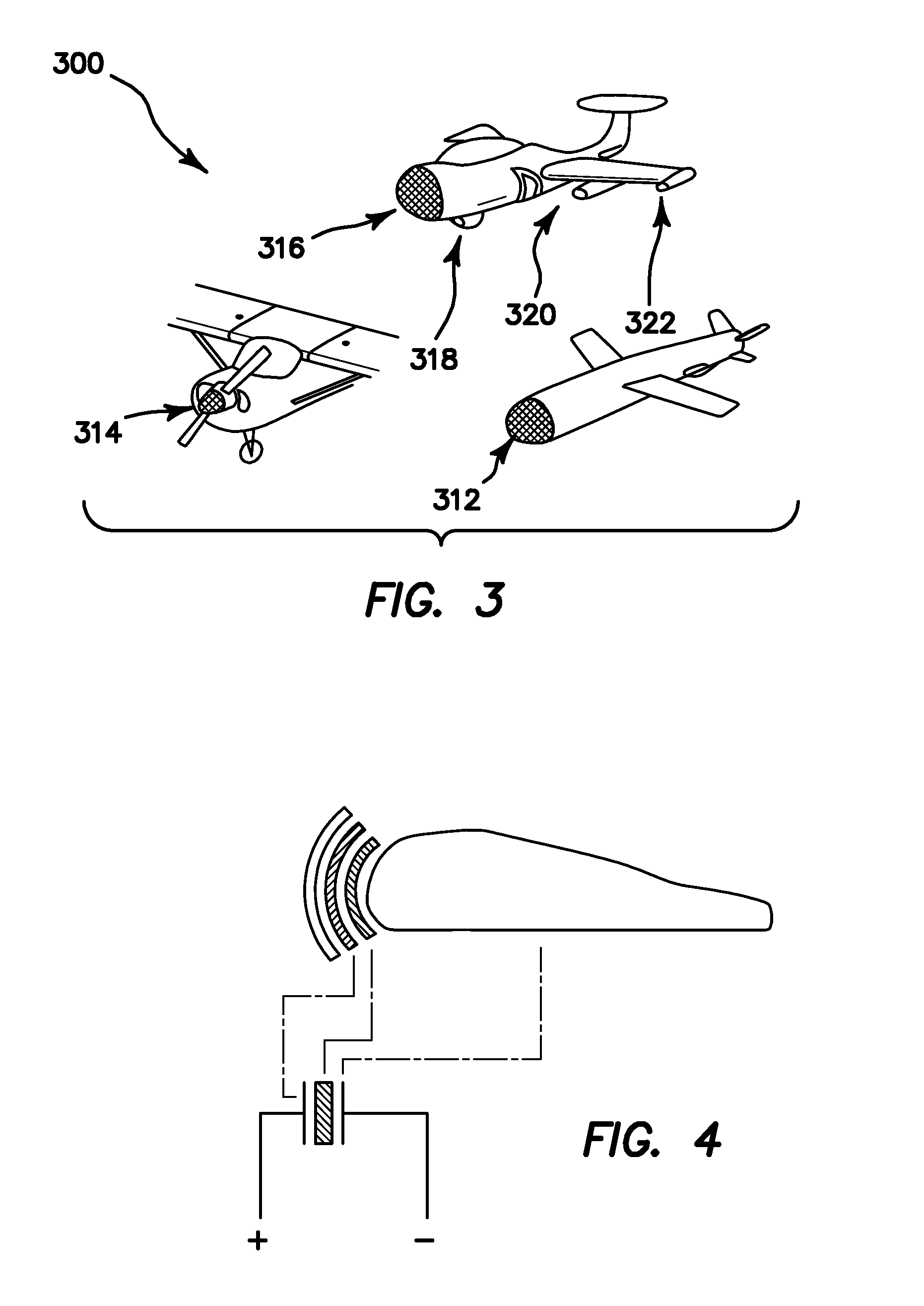
[0053]One aspect of the invention provides a method for anti-icing, de-icing, and a heating system for aircraft wings and forward facing aerodynamic surfaces, for example, wind turbines, propeller spinners, aircraft radomes, and nosecones. The invention comprises a first heated section near the central stagnation zone to prevent cupped or shelled icing from forming there, and at least one upper and lower heater section in areas aft of the central heater. Typically, runoff melt-water from the central heater will refreeze together with other ice accumulation. By periodically activating the upper and lower heaters to melt or break-up the ice-to-surface interface, the accumulated ice will be removed by aerodynamic (or other) forces.

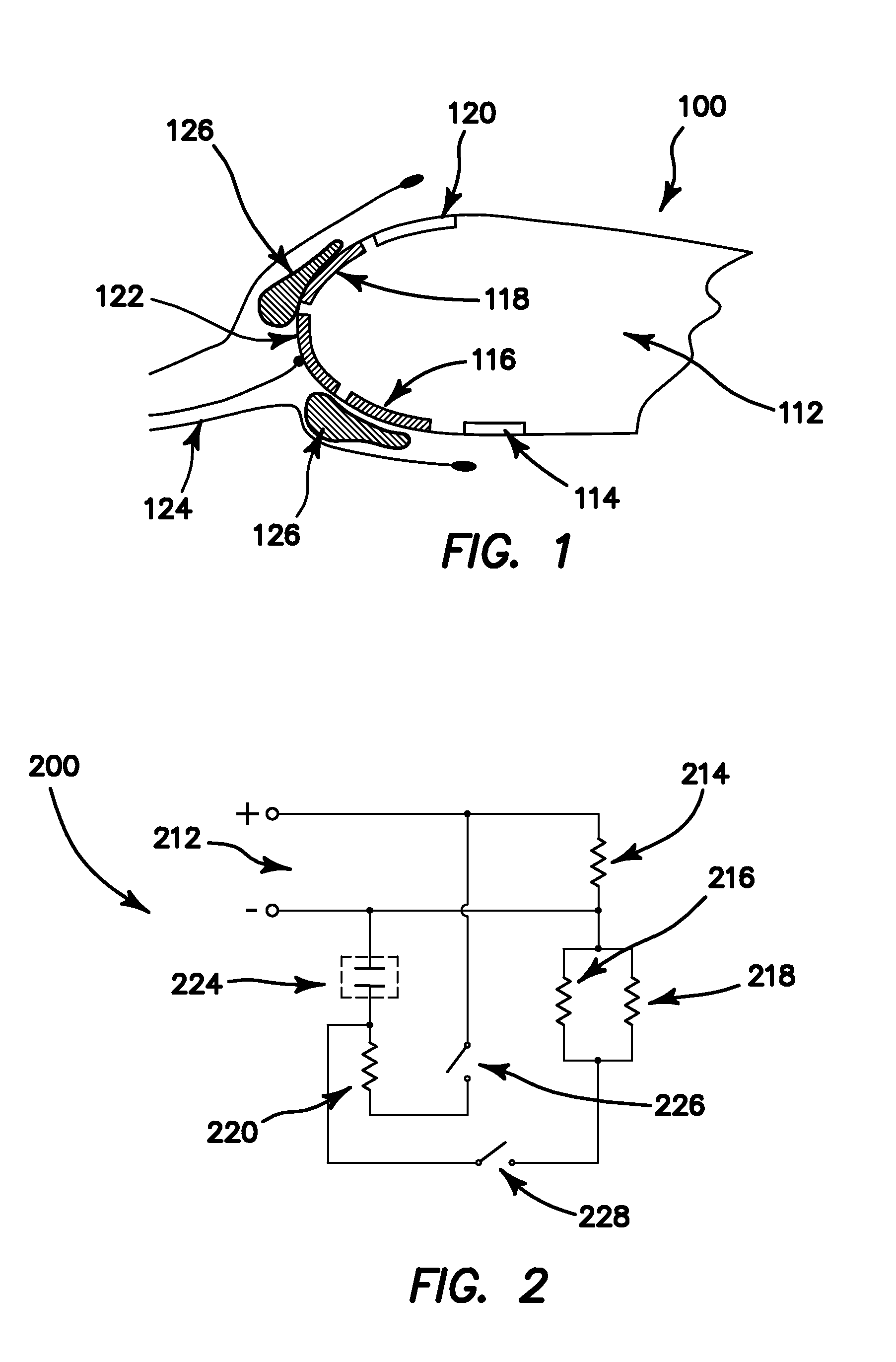
[0054]FIG. 1 shows a schematic 100 of a cross-section of an aircraft wing 112, central heater 122 at the stagnation zone, lower heaters 114 and 116, upper heaters 118 and 120, ice layer 126, and aerodynamic streamlines 124. As an alternative arrangement, FIG....


PUM


Abstract

Anti-icing methods and aerodynamic structures having laminated resistive heaters for de-icing are described. Several of the inventive aspects utilize laminated resistive heaters comprising a carbon nanotube layer and/or capacitors to store and supply electricity. The invention also includes methods of making aerodynamic structures having de-icing or anti-icing functionality.

Description

RELATED APPLICATIONS[0001]This application claims priority to U.S. Provisional Patent Application Ser. No. 61 / 429,106 filed 31 Dec. 2010.ABSTRACT[0002]Anti-icing methods and aerodynamic structures having laminated resistive heaters for de-icing are described. Several of the inventive aspects utilize laminated resistive heaters comprising a carbon nanotube layer and / or capacitors to store and supply electricity. The invention also includes methods of making aerodynamic structures having de-icing or anti-icing functionality.INTRODUCTION[0003]Forward facing aerodynamic surfaces, for example, wind turbines, propeller spinners, radomes, when exposed to atmospheric icing conditions are susceptible to ice build-up on the leading edge surface. If not removed, this accumulated ice can add excessive weight to the structure and alter the airfoil configuration. For aircraft airfoils, this can cause undesirable and / or dangerous flying performance. Ice build-up on the outside surface of a radome ...

Claims


Application Information

Patent Timeline
Patent Type & Authority Applications(United States)
IPC IPC(8): B64D15/12
CPCB64D15/12H05B1/0236H05B3/26H05B2203/013H05B2214/02H05B2214/04H05B6/10H05B2203/007B82Y30/00H01Q1/02H01Q1/368H01Q9/0407H01Q9/285H10K85/221
Inventor BURTON, BRETT R.FEIER, IOAN I.LASTRAPES, TIMOTHY J.
Owner BATTELLE MEMORIAL INST
Why Eureka
Try Eureka