Shockwave catheter system with energy control

Active Publication Date: 2014-03-13
SHOCKWAVE MEDICAL
View PDF2 Cites 56 Cited by
  • Summary
  • Abstract
  • Description
  • Claims
  • Application Information

AI Technical Summary

Benefits of technology

[0019]In a further embodiment, a system includes a catheter including an elongated carrier and a balloon about the carrier in sealed relation thereto. The balloon is arranged to receive a fluid therein that inflates the balloon. The catheter further includes first and second electrodes within the balloon arranged to receive there-across a high electrical voltage at an initial low current to cause an electrical arc to form across the first and second electrodes within the balloon. The electrical arc creates a steam bubble within the liquid, a high current to flow through the first and second electrodes, and a mechanical shock wave within the balloon. The steam bubble increases the temperature of the fluid. The system further includes a temperature sensor within the ballo

Problems solved by technology

With such pressures comes trauma to the vessel wall which can contribute to vessel rebound, dissection, thrombus formation, and a high level of restenosis.
Non-concentric calcified lesions can result in undue stress to the free wall of the vessel when exposed to high pressures.
That energy is then released and results in the rapid expansion of the balloon to its maximum dimension and may stress and injure the vessel walls.
Unfortunately, spherical bubble configuration requires a substantially larger space than is available in a balloon that must fit into a calcified vein or artery or even a ureter.
As a result, for angioplasty or other cardiac and non-cardiac applications of shock waves, the trailing edge shock wave cannot be reliably relied upon to produce consistent results.
Since the size of the el

Method used


Image

  • Shockwave catheter system with energy control
  • Shockwave catheter system with energy control
  • Shockwave catheter system with energy control

Examples


Example

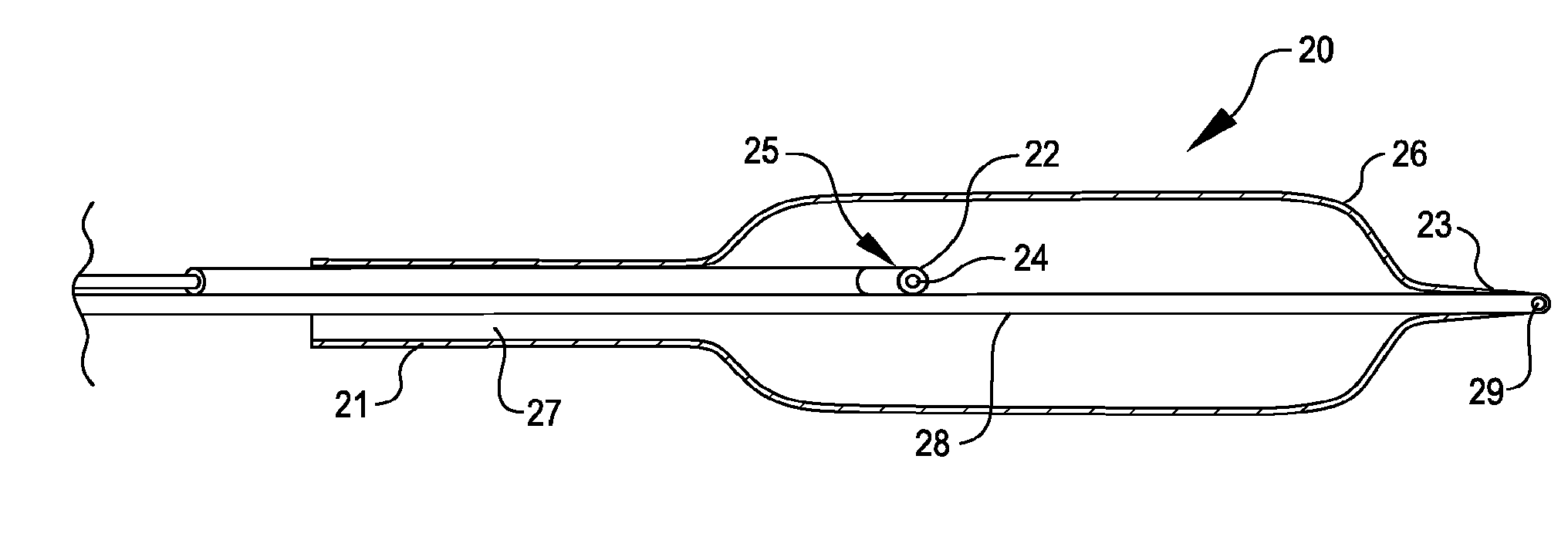
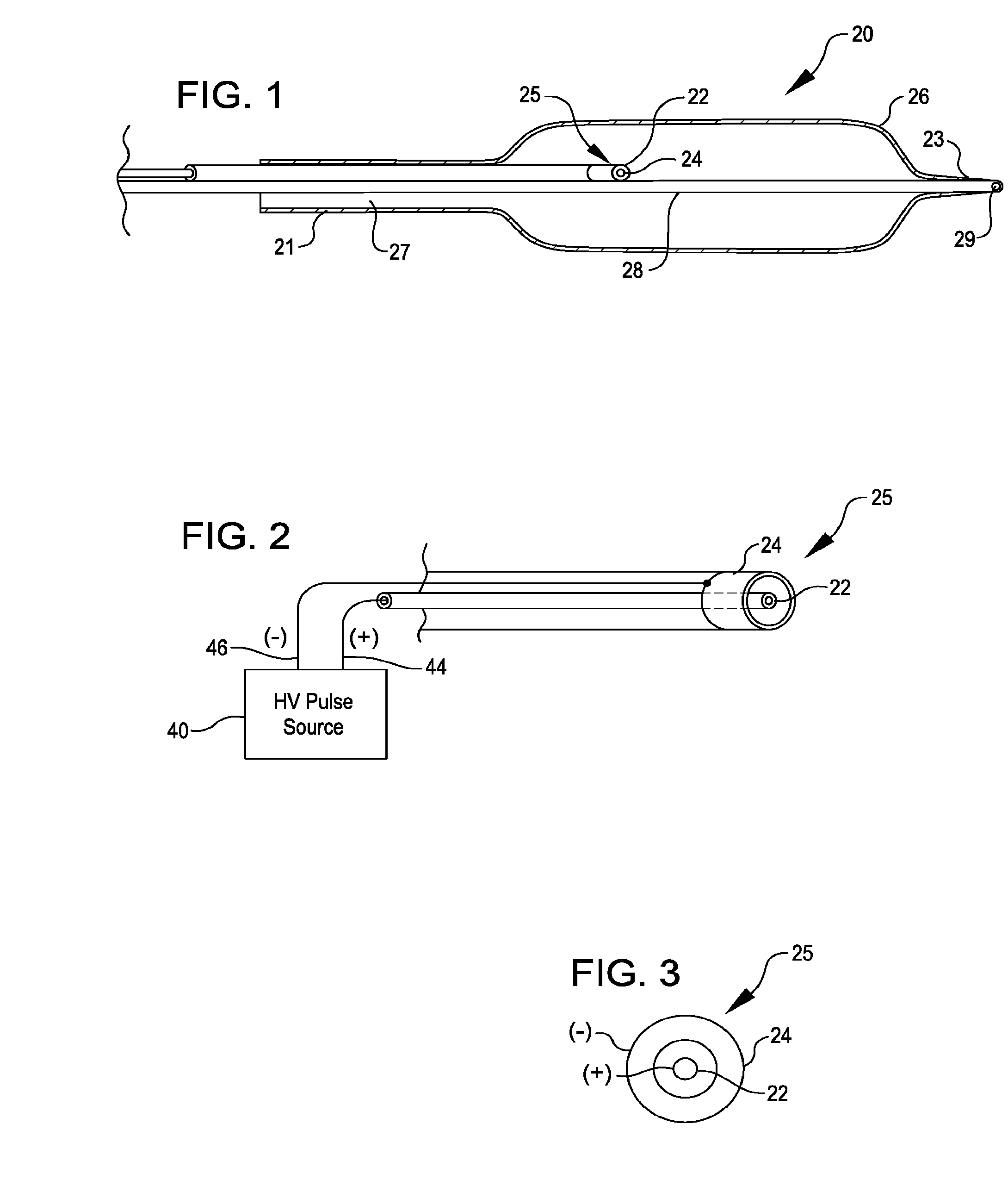
[0055]FIG. 1 is a simplified side view of an angioplasty balloon catheter 20 of the type that may utilize various embodiments of the invention to advantage. The catheter 20 includes an elongated carrier, such as a hollow sheath 21, a dilating balloon 26 formed about the sheath 21 in sealed relation thereto and a guide wire member 28 to which the balloon is sealed at a seal 23. The guide wire member has a longitudinal lumen 29 through which a guide wire (not shown) may be received for directing the catheter 20 to a desired location within a vein or artery, for example.

[0056]The sheath 21 forms with the guide wire member 28 a channel 27 through which fluid, such as saline, may be admitted into the balloon to inflate the balloon. The channel 27 further permits the balloon 26 to be provided with an electrode pair 25 including electrodes 22 and 24 within the fluid filled balloon 26.

[0057]As may be seen in FIG. 2, the electrodes 22 and 24 are attached to a source 40 of high voltage pulses...


PUM


Abstract

A system that breaks calcium in a liquid includes a catheter including first and second electrodes arranged to receive there-across a high electrical voltage at an initial low current. The high electrical voltage causes an electrical arc to form across the electrodes creating a gas bubble within the liquid, a high current to flow through the electrodes, and a mechanical shock wave. A power source provides the electrodes with the high electrical voltage at the initial current and terminates the high electrical voltage in response to the high current flow through the electrodes.

Description

CROSS-REFERENCE TO RELATED APPLICATIONS[0001]This application is a continuation application of U.S. application Ser. No. 13 / 615,107, entitled SHOCKWAVE CATHETER SYSTEM WITH ENERGY CONTROL, filed Sep. 13, 2012, which is hereby incorporated by reference in its entirety and for all purposes.BACKGROUND OF THE INVENTION[0002]The present invention relates to a treatment system for percutaneous coronary angioplasty or peripheral angioplasty in which a dilation catheter is used to cross a lesion in order to dilate the lesion and restore normal blood flow in the artery. It is particularly useful when the lesion is a calcified lesion in the wall of the artery. Calcified lesions require high pressures (sometimes as high as 10-15 or even 30 atmospheres) to break the calcified plaque and push it back into the vessel wall. With such pressures comes trauma to the vessel wall which can contribute to vessel rebound, dissection, thrombus formation, and a high level of restenosis. Non-concentric calci...

Claims


Application Information

Patent Timeline
IPC IPC(8): A61B17/22
CPCA61B17/22022A61B2017/22025A61B2017/00084A61B2017/00154A61B2017/22038A61B2017/22051A61B17/22A61B17/225A61B2017/00039A61B2017/22065
Inventor HAKALA, DOUGADAMS, JOHN M.HOLMBERG, RANDY
Owner SHOCKWAVE MEDICAL
Why Eureka
Try Eureka