

Control device, actuator including control device, image blur correction device, replacement lens, imaging device and automatic stage
- Summary
- Abstract
- Description
- Claims
- Application Information
AI Technical Summary
Benefits of technology
Problems solved by technology
Method used
Image


Examples
embodiment 1
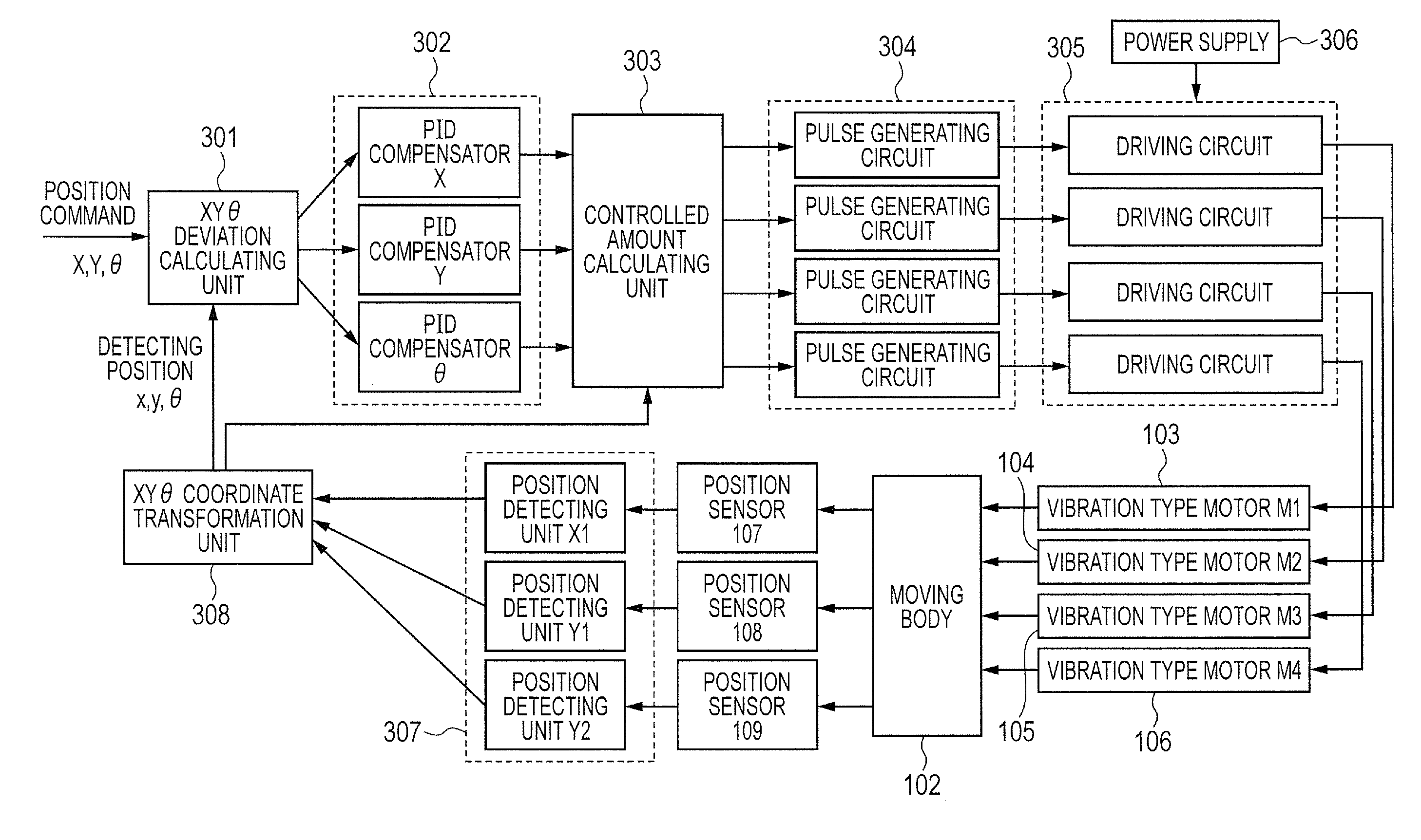
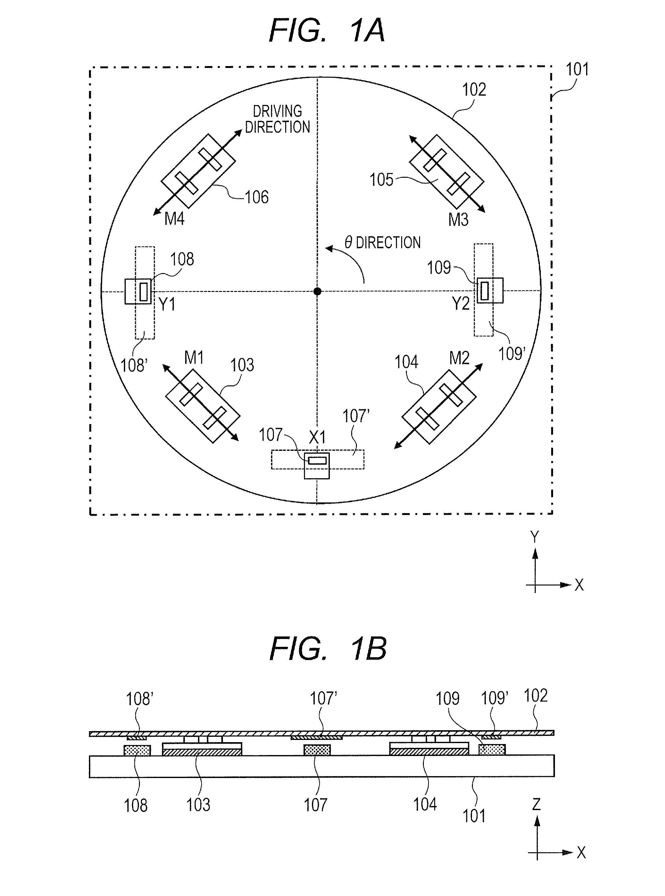
[0070]The following exemplifies a vibration type multi-degree freedom driving device as an actuator (multi-degree freedom driving device) capable of driving a moving body multidirectionally in one embodiment of the present invention.
[0071]The following describes, as one embodiment of the present invention, an exemplary structure where a multi-degree freedom driving device including a motor control device of the present invention is applied to a vibration absorption mechanism (image blur correction device) for a camera as an optical apparatus. Although the present embodiment describes the exemplary structure of installation in a camera, the present invention is not limited to this, and is applicable to a control device at a stage or the like.
[0072]A vibration type multi-degree freedom driving device of the present, embodiment includes a plurality of vibrators configured so that vibrations are excited by the application of AC voltage.
[0073]Then the moving body in contact with the plur...
embodiment 2
[0159]Embodiment 1 describes the example of using a vibration type motor as a motor, and the present invention is not limited to this and may use other types of motors.
[0160]Referring to FIG. 13, the present embodiment describes an exemplary configuration which is different from Embodiment 1 only in the driving means. Embodiment 1 describes the case of using a vibration type multi-degree freedom driving device including vibration type motors as motors. Such a vibration type motor is configured so that the application of a driving signal to an electric-mechanical energy conversion element provided in a vibrator excites an elliptic motion at the vibrator, the elliptic motion resulting from two bending modes including first and second bending modes whose nodal lines cross each other substantially orthogonally, and a driving force occurs due to friction of the vibrator with a contact part.
[0161]The present embodiment describes an example of using, instead of such a vibration type motor,...
embodiment 3
[0171]The following describes an example where the motor control device of the present invention is applied to an imaging device (optical apparatus) such as a camera. Referring to FIG. 15, the following describes an example where a vibration type motor to drive a lens for autofocusing is assembled in a lens barrel of the imaging device.
[0172]FIG. 15 is a cross-sectional view of a camera as an imaging device to correct image blur by a correction lens. The camera of FIG. 15 has an imaging function of motion pictures and stationary pictures. The camera includes a lens barrel 61 and a camera body 62. The camera further includes a correction optical device 68 built in the lens barrel 61. The correction optical device 68 of the present embodiment includes a correction lens 31 and a moving plate (movable member) 32 holding the correction lens 31, and the moving plate 32 performs translation motion in a plane orthogonal to an optical axis 40 of the correction optical device by a driving dev...
PUM
 Abstract
Description
Claims
Application Information