Radioactive contaminant container

a technology of contaminated containers and containers, applied in the field of containers, can solve the problems of difficult safe stacking of containers thereon, adversely affecting the environment, and all radioactive contaminants cannot be immediately purified, so as to enhance the radiation shielding efficiency, and increase the thickness of the wall of adjacent places

Inactive Publication Date: 2014-03-20
KAWAHARA TECHN RES
View PDF0 Cites 9 Cited by
  • Summary
  • Abstract
  • Description
  • Claims
  • Application Information

AI Technical Summary

Benefits of technology

[0029]If the containing space of the radioactive contaminant container according to the present invention is configured to contain other multiple radioactive contaminant containers according to the present invention, the radioactive contaminants contained inside the multiple radioactive contaminant containers are doubly contained in the radioactive contaminant container. Accordingly, it is possible to further enhance the radiation shielding efficiency. Furthermore, the outer shape of the wall in the radioactive contaminant container containing the multiple containers is the hexagonal cylinder or the substantially hexagonal cylinder. Accordingly, the thickness of the wall of the adjacent places is increased by the juxtaposition. Therefore, as described above, it is possible to further enhance the radiation shielding efficiency.
[0030]If the first recess is disposed on three surfaces which are not adjacent to each other within six surfaces extending in the axial direction of the hexagonal cylinder or the substantially hexagonal cylinder, and if the handle for attaching the wire rope for transportation is disposed in the first recess, when lifting, transporting and installing the radioactive contaminant container, the radioactive contaminant container can be lifted, transported and installed with a good balance.

Problems solved by technology

However, the mobile radiation shielding container disclosed in Japanese Unexamined Patent Application Publication No. 2007-147580 is proposed on the premise that the container is used in a medical field, and is not intended to store a large amount of radioactive contaminants.
For example, when an accident of a nuclear power plant results in a large amount of the radioactive contaminants, all of the radioactive contaminants cannot be immediately purified.
Accordingly, it is apprehended that the lead adversely affects the environment.
However, since the mobile radiation shielding container disclosed in Japanese Unexamined Patent Application Publication No. 2007-147580 has the attached caster, it is difficult to safely stack the container thereon.

Method used


Image

  • Radioactive contaminant container
  • Radioactive contaminant container
  • Radioactive contaminant container

Examples


first embodiment

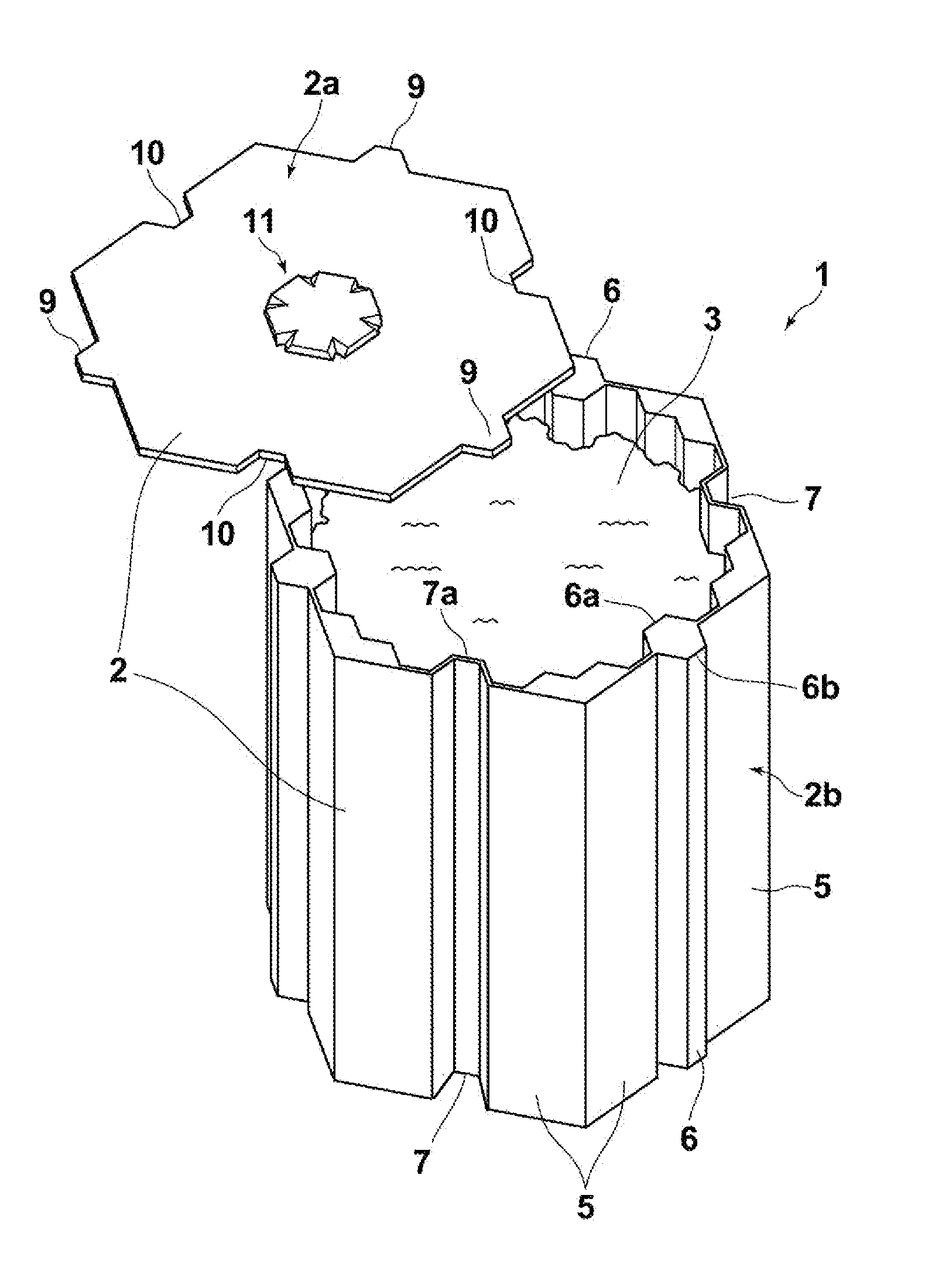
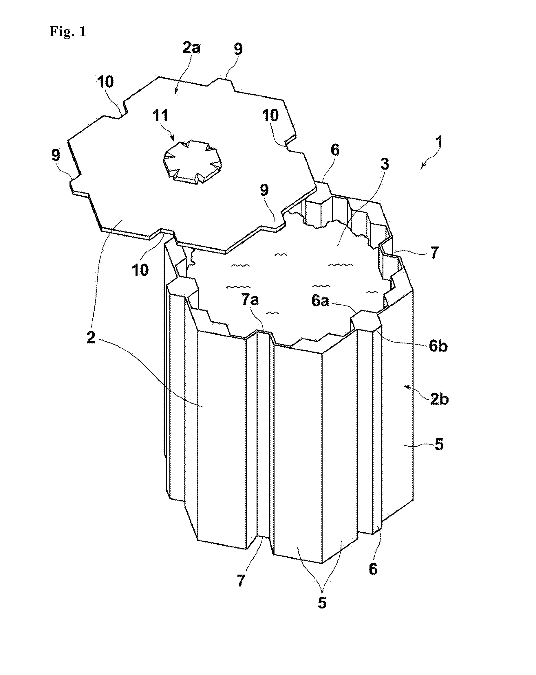
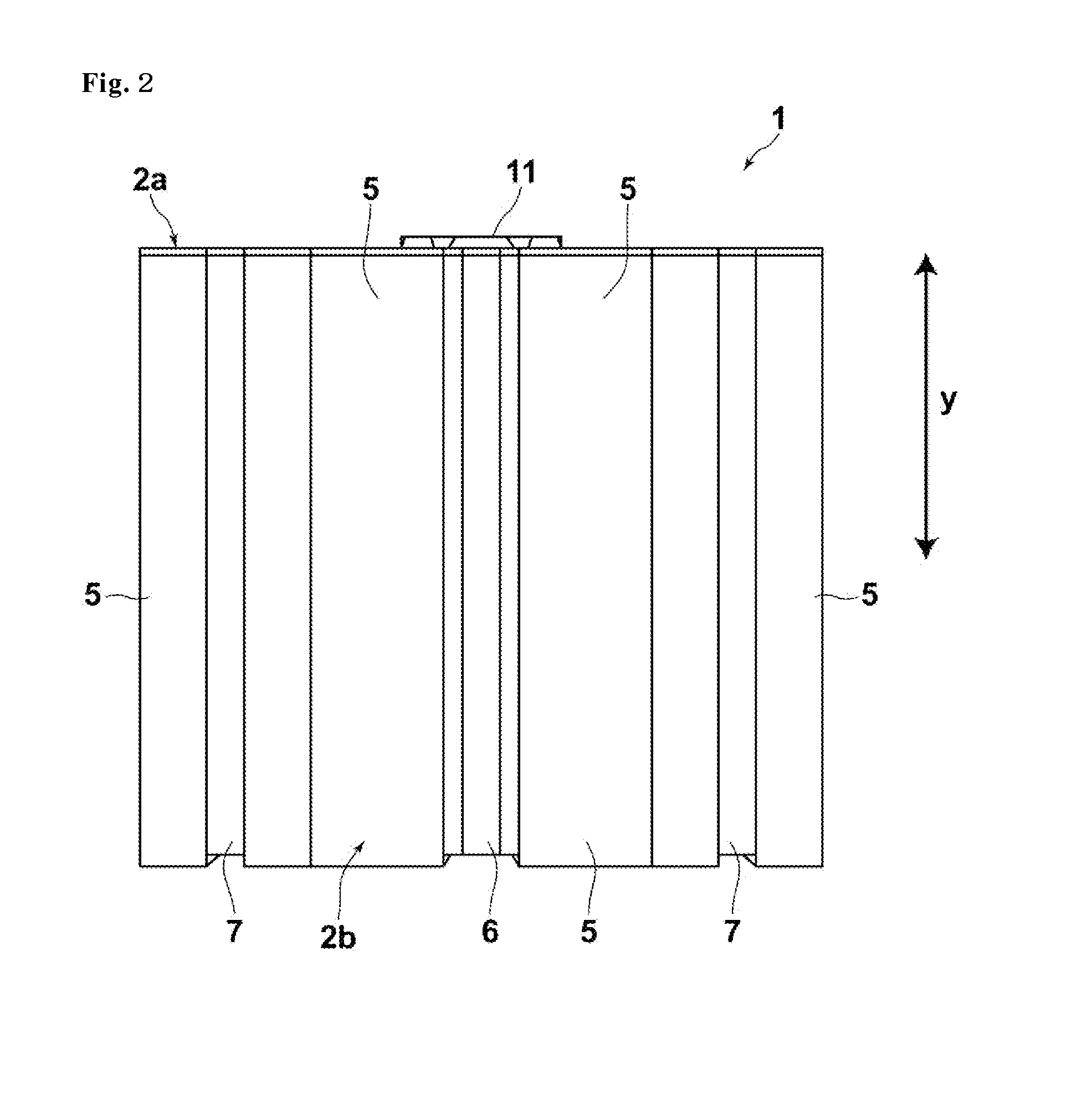
[0048]Hereinafter, an embodiment of the present invention will be described with reference to the accompanying drawings. FIG. 1 illustrates a perspective view of a radioactive contaminant container according to the first embodiment, and FIG. 2 illustrates a front view of the radioactive contaminant container 1. A radioactive contaminant container 1 includes walls 2 which define a containing space for containing radioactive contaminants 3 such as radioactively contaminated soil and radioactively contaminated ashes. The walls 2 shield at least a portion of radiation irradiated from the radioactive contaminants 3. The walls 2 of the radioactive contaminant container 1 have an outer shape of a substantially hexagonal cylinder.

[0049]The walls 2 include a detachable lid 2a disposed to be capable of introducing the radioactive contaminants 3 and a main body 2b. In the radioactive contaminant container 1 according to the first embodiment, as illustrated in FIG. 2, in a positional relationsh...

example 1

of Radiation Shielding Materials

[0083]SiO2 (manufactured by Iwai Chemicals Co., Ltd) of 40 mass %, SrCO3 (manufactured by Honjo Chemical Corporation) of 38.2 mass %, MgO (manufactured by Ube Material Industries, LTD.) of 20 mass %, Eu2O3 (manufactured by NeoMag Co., Ltd.) of 0.4 mass %, Dy2O3 (manufactured by NeoMag Co., Ltd.) of 0.4 mass % and H3BO3 (manufactured by Iwai Chemicals Co., Ltd) of 1 mass % were placed in a ball mill mixer, and were mixed for one hour. Then, the materials were placed in an electric furnace, and firing was performed under the conditions of air atmosphere, 1,300° C. and two hours. After the firing, the materials were naturally cooled to a room temperature, and were pulverized by using the ball mill mixer so that an average particle size thereof became 7 μm. In this manner, the radiation shielding materials in Example 1 were obtained.

[0084]A composition ratio of the radiation shielding materials in Example 1 was measured. The measured result was Si of 13.3...

example 2

of Radiation Shielding Materials

[0086]For the radiation shielding materials obtained in Example 1, sintering was further performed at 1,000° C. for approximately 30 minutes by using a plasma sintering machine (manufactured by SPS Syntax Inc., Model No.: SPS-1030). After the sintering, the radiation shielding materials were naturally cooled to a room temperature, and radiation shielding materials (pellet shape and thickness of 3 mm) in Example 2 were obtained.

Comparative Examples of Radiation Shielding Materials

[0087]A lead plate (thickness of 0.3 mm, commercially available) and an aluminum plate (thickness of 3 mm, commercially available) were respectively used in Comparative Example 1 and Comparative Example 2. X-ray Shielding Performance of Radiation Shielding Materials (X-ray Transmission Measurement)

[0088]The radiation shielding materials in Example 1 were further processed in a pellet shape (thickness of 3.95 mm) by using a press machine. According to a transmission method, an ...


PUM


Abstract

Disclosed is a radioactive contaminant container including a wall that defines a containing space for containing radioactive contaminants and shields at least a portion of radiation irradiated from the radioactive contaminants, and the wall has an outer shape of a hexagonal cylinder or a substantially hexagonal cylinder.

Description

BACKGROUND OF THE INVENTION[0001]1. Field of the Invention[0002]The present invention relates to a container, and particularly relates to a radioactive contaminant container for containing radioactive contaminants.[0003]2. Background Art[0004]In the related art, a radioactive contaminant container for safely containing radioactive contaminants has been known (for example, refer to Japanese Unexamined Patent Application Publication No. 2007-147580). Japanese Unexamined Patent Application Publication No. 2007-147580 discloses a mobile radiation shielding container formed in order to safely reserve radioactive wastes generated in a medical field for waste treatment or to store radioactive materials. The mobile radiation shielding container is a heavy radiation shielding container formed by heavy metals such as lead in order to contain a radioactive waste introducing receptacle or a radioactive material storing bucket. The radiation shielding container disclosed in Japanese Unexamined P...

Claims


Application Information

Patent Timeline
Patent Type & Authority Applications(United States)
IPC IPC(8): G21F3/00
CPCG21F3/00G21F1/125G21F5/002G21F5/005G21F5/06G21F5/015
Inventor KAWAHARA, SATOSHI
Owner KAWAHARA TECHN RES
Why Eureka
Try Eureka